Motor stator and motor stator manufacturing method

a technology of motor stator and manufacturing method, which is applied in the direction of windings, dynamo-electric components, magnetic circuit shapes/forms/construction, etc., can solve the problems of high cost, long welding time, and the possibility of enamel covering thin plates being burned during welding, so as to reduce the range of slant surfaces that contact with each other. , the effect of reducing the contact resistan

Inactive Publication Date: 2009-09-17
TOYOTA JIDOSHA KK
View PDF20 Cites 21 Cited by
  • Summary
  • Abstract
  • Description
  • Claims
  • Application Information

AI Technical Summary

Benefits of technology

[0025]According to the configuration (2), the end portion of each thin plate and the connecting portion of each connecting thin plate are tapered in thickness to have slanted surfaces on one sides, and the end portion of each thin plate and the connecting portion of each connecting thin plate are provided with an insulating layer on a non-slanted surface, and an adhesive is applied in a layer on at least the slanted surface of the connecting portion of the connecting thin plate. Accordingly, the area of the slanted surface can be larger to allow the adhesive to be applied wider, leading to a reduction in the contact resistance at joints between the conductors. Further, the insulating layer is formed on the non-slanted surface, so that insulation between the thin plates of each laminated conductor can be easily ensured.
[0026]In particular, the end portion of each thin plate and the connecting portion of each connecting thin plates are wholly tapered in thickness to have a slanted surface. This makes it possible to reduce the range where the slanted surfaces contact with each other.

Problems solved by technology

Therefore, when joints between thin plates are welded as described in JP2001-178053A, even if a welding technique such as TIG welding or laser welding is employed, the position of a TIG welding torch or laser welding spot must be accurately adjusted to all joints, resulting in a long welding time and higher cost.
In addition, the heat generated during welding might burn the enamel covering the thin plates.

Method used


Image

  • Motor stator and motor stator manufacturing method
  • Motor stator and motor stator manufacturing method
  • Motor stator and motor stator manufacturing method

Examples


Embodiment Construction

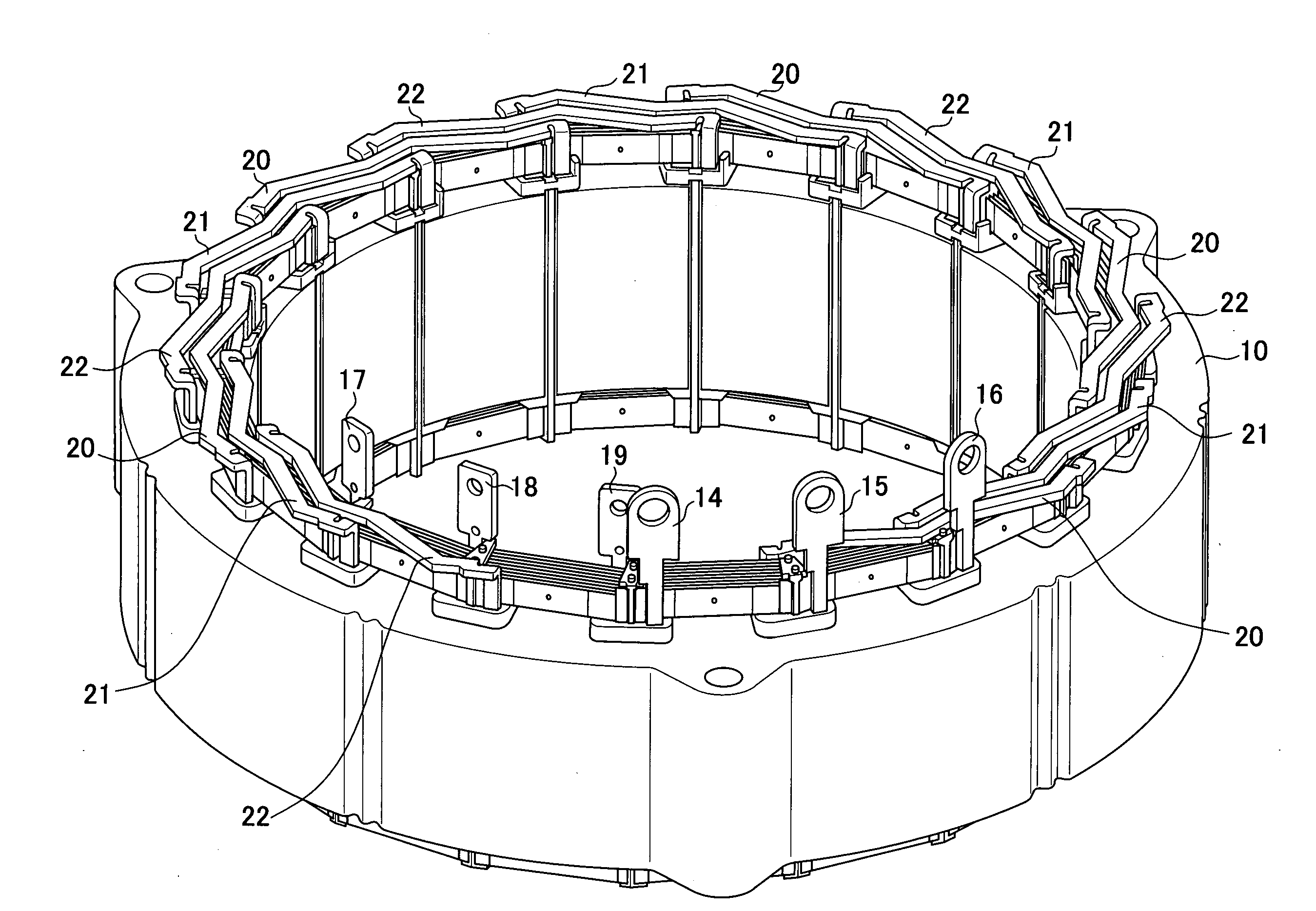
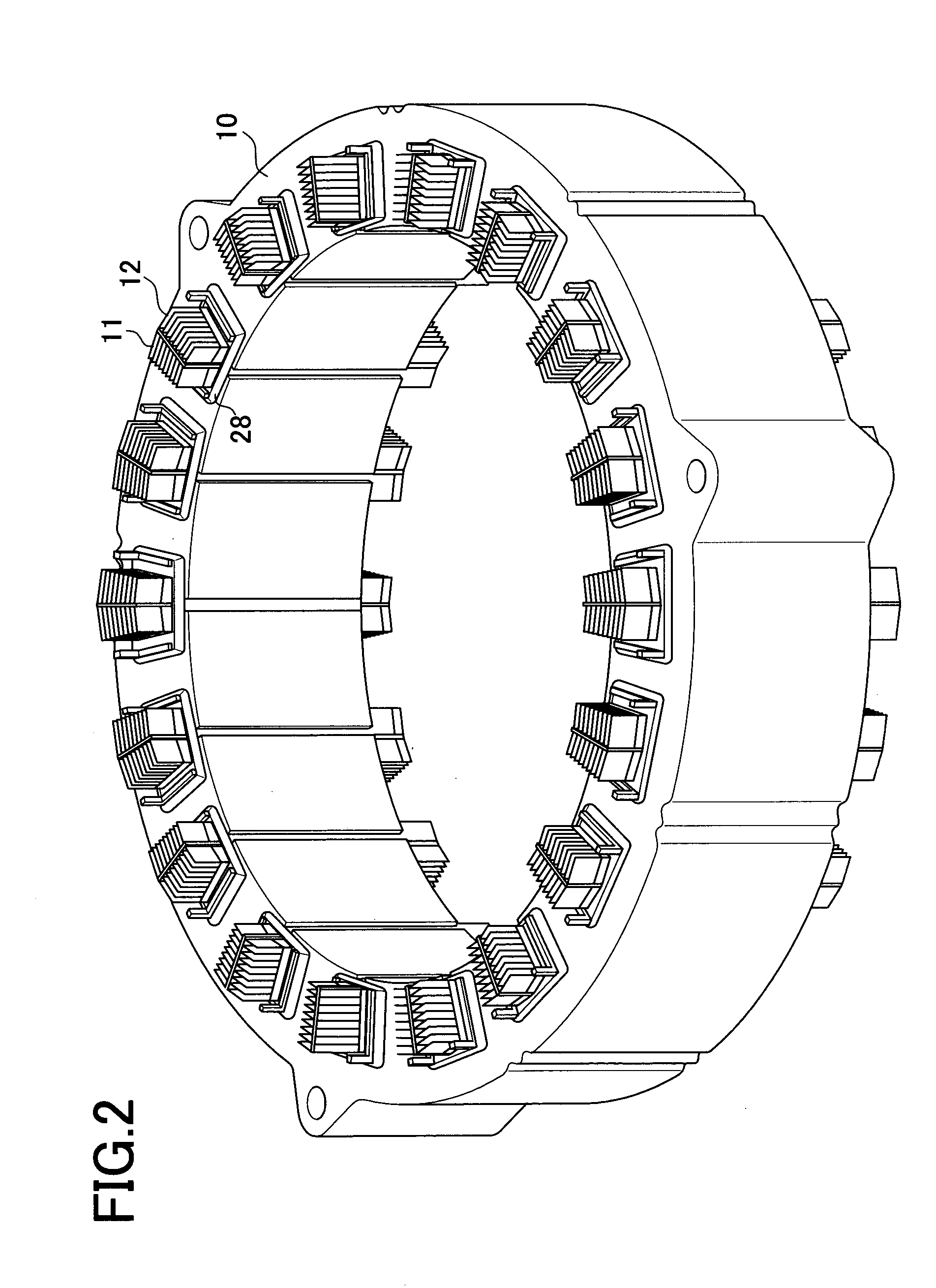
[0055]A motor stator of a first embodiment of the present invention will be described in detail referring to accompanying drawings. It is to be noted that the number of components and the size of each component in the following explanations are merely examples and may be changed appropriately. FIG. 2 is a perspective view of a stator core 10 in which a first laminated conductors 11 and a second laminated conductors 12 are fitted.

[0056]FIG. 8 is a perspective view of the stator core 10. The stator core 10 is a laminate of plural flat electromagnetic steel plates, taking the form of a hollow cylinder. Eighteen slots 24 and eighteen teeth portions 25 each formed between slots 24 are provided in an inner periphery of the stator core 10. The stator core 10 has three bolt holes 26.

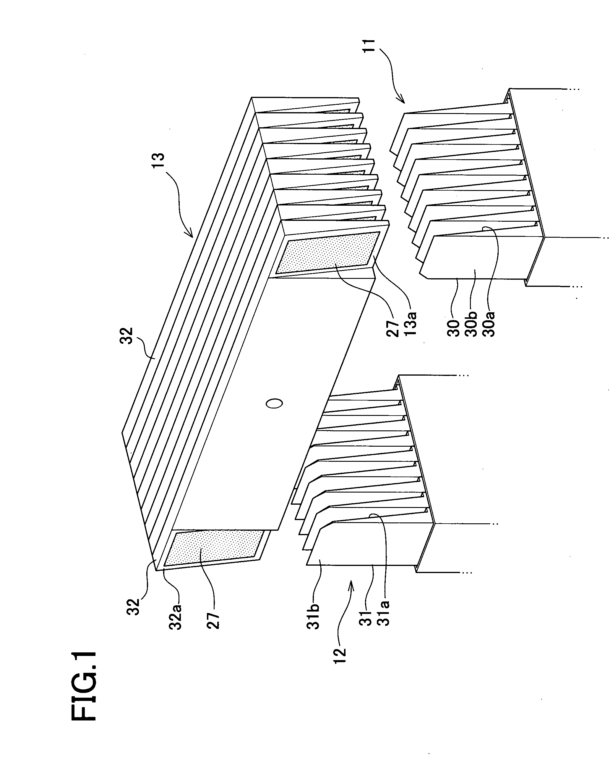
[0057]FIG. 5 shows a perspective view of a second laminated conductor 12 formed in such a way that nine thin plates 31 each having both end portions tapered in side view (in thickness) with slanted surfaces 31a ...


PUM

PropertyMeasurementUnit
angleaaaaaaaaaa
thicknessaaaaaaaaaa
inclination angleaaaaaaaaaa

Abstract

A stator for motor comprises a stator core formed with a plurality of slots in an inner periphery thereof, a plurality of first laminated conductors each including a plurality of laminated thin plates in each slot, a plurality of second laminated conductors each including a plurality of laminated thin plates inserted in each slot, and an end connecting conductor including a plurality of connecting thin plates each having a connecting portion for connecting an end portion of each laminated thin plate of the first laminated conductor in one slot and an end portion of each laminated thin plate of the second laminated conductor in another slot. The thin plates and the connecting portion of each connecting plate are tapered in thickness.

Description

TECHNICAL FIELD[0001]The present invention relates to a structure of a stator used in a motor and more particularly to a motor stator structure which uses laminated conductors.BACKGROUND ART[0002]Heretofore, mainstream stators for use in motors have been winding type stators in which enamel-coated copper wires are inserted into slots in an inner periphery of a stator core and an enamel-coated copper wire is wound around a teeth portion formed between slots. Recently, a stator using laminated conductors for the purposes of stator compactness and high power output as described in JP2001-178053A has also been proposed.[0003]The stator using laminated conductors is more advantageous in two points than the winding type stator. The first advantage is that by adopting a method whereby laminated conductors inserted in slots are joined using an end connecting conductor formed of a laminate of thin plates, the thickness of coil end portions which would expand in the case of the winding type c...

Claims


Application Information

Patent Timeline
Patent Type & Authority Applications(United States)
IPC IPC(8): H02K3/12H02K15/085
CPCH02K3/12H02K3/18Y10T29/49009H02K3/522H02K2203/09H02K3/48H02K1/16H02K3/34H02K15/024H02K15/04H02K15/085
Inventor TATEBE, KATSUHIKO
Owner TOYOTA JIDOSHA KK
Why Eureka
Try Eureka