Stator of electric motor and cooling structure of electric rotating machine

a technology of electric motors and stators, which is applied in the direction of cooling/ventilation arrangements, windings, and magnetic circuit shapes/forms/construction, etc., can solve the problems of limited contact between the stator and the heat source, limited time during continuous driving of the motor at a high power, and inability to provide efficient cooling. , to achieve the effect of reducing air space, increasing the thermal conduction amount between the tooth and the insulation member, and reducing the thermal resistan

Active Publication Date: 2020-02-25
KUBOTA CORP
View PDF74 Cites 5 Cited by
  • Summary
  • Abstract
  • Description
  • Claims
  • Application Information

AI Technical Summary

Benefits of technology

According to the stator for the electric motor of the present invention, the thermal conduction amount between the tooth and the insulation member is increased, and the thermal resistance between the tooth and the insulation member is reduced.
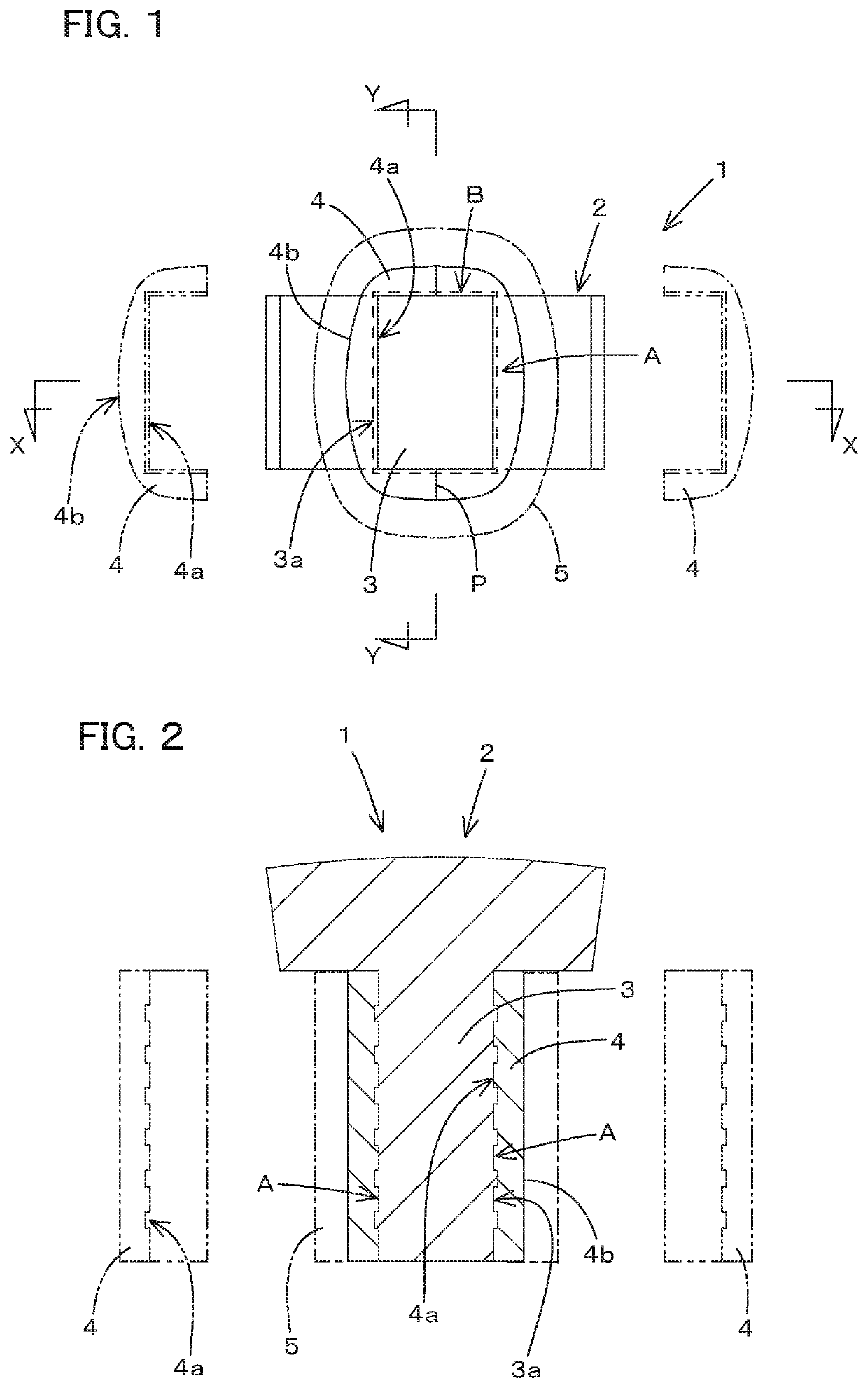
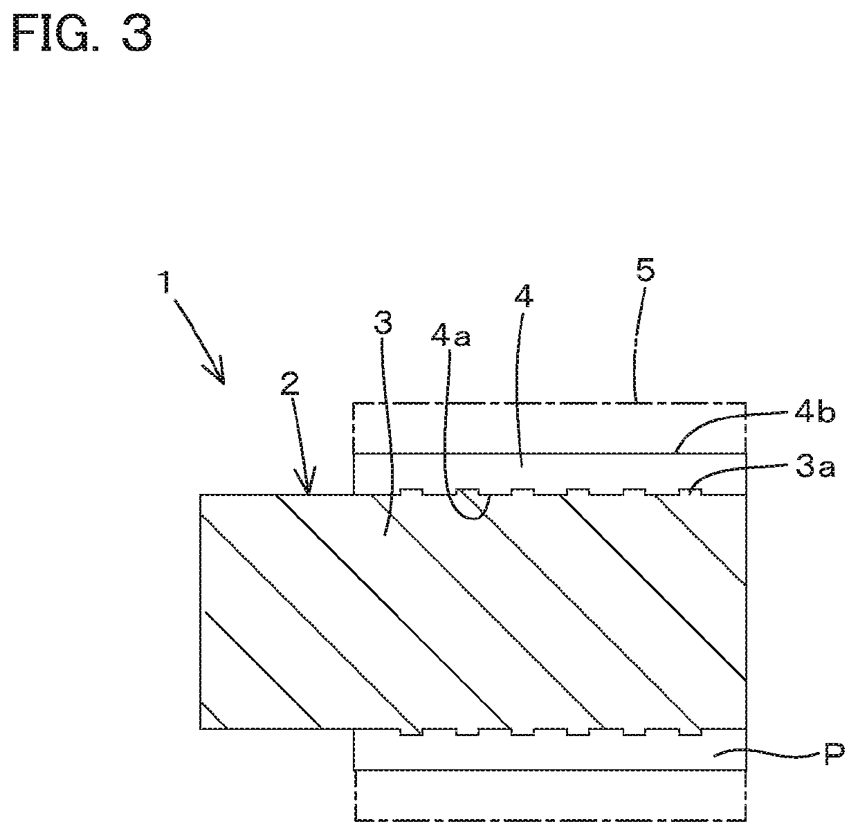
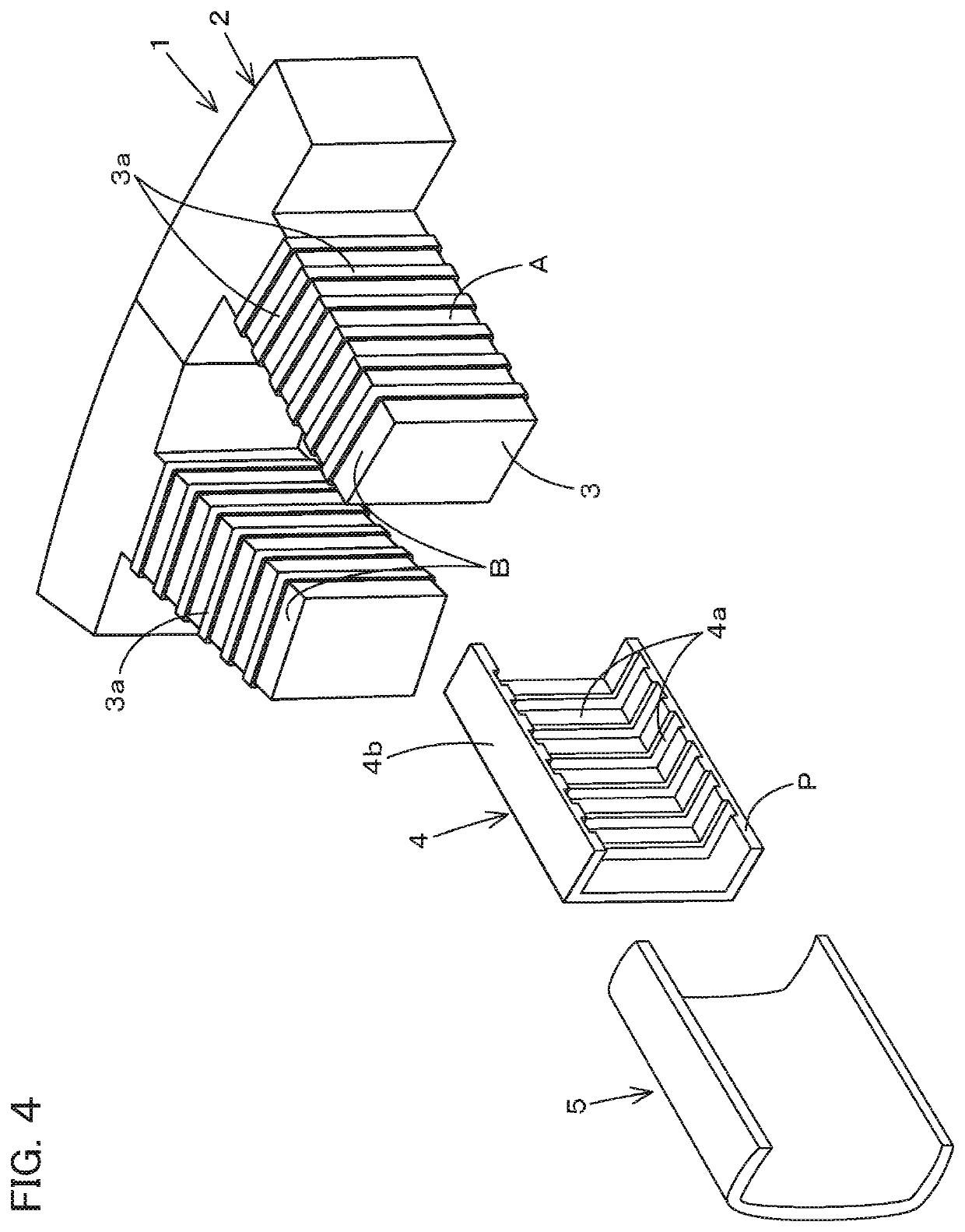
That is, the concave-convex portion 3a is formed at least on the circumferential surface A among the circumferential surface A and an axial surface B of the tooth 3, and the concave-convex portion 4a is formed on the inner surface of the insulation member 4, the concave-convex portion 4a being configured to be fitted to the concave-convex portion 3a. In this manner, the inner surface of the insulation member 4 is tightly attached to the circumferential surface A of the tooth 3 with a large area, thus the air space is reduced, and thereby the thermal conduction amount between the inner surface and the circumferential surface A is increased and the thermal resistance between the inner surface and the circumferential surface A is reduced.
In addition, the outer surface 4b of the insulation member 4 is formed to have a circular arc shape intermediately bulging in a winding direction of the winding wire 5. In this manner, the air space between the winding wire 5 and the outer surface 4b of the insulation member 4 is reduced, and thereby the thermal conduction amount between the winding wire 5 and the outer surface 4b is increased and the thermal resistance between the winding wire 5 and the outer surface 4b is reduced.
In addition, the winding wire 5 has a circular shape in a cross section, the outer surface 4b includes the spiral concave-convex portion (a spiral attachment portion including a concave portion and a convex portion) 4c fitted to the winding wire 5, and a plurality of the attachment portions 4c are formed and arranged in a direction of diameter of the tooth 3. Thus, the outer surface 4b of the insulation member 4 is tightly attached to the winding wire 5 with a large area. In this manner, the air space between the winding wire 5 and the outer surface 4b of the insulation member 4 is reduced, and thereby the thermal conduction amount between the winding wire 5 and the outer surface 4b is increased and the thermal resistance between the winding wire 5 and the outer surface 4b is reduced.
In addition, the insulation member 4 is split to have a split shape, one of the insulation members 4 of the split shape is opposed to the other one of the insulation members 4, and both of the insulation members 4 opposed to each other surround the circumferential surface A and the axial surface B of the tooth 3. In this manner, the insulation members 4 are manufactured and attached extremely easily.
In addition, according to the cooling structure for the electric rotating machine, a strength of the water jacket of the electric rotating machine is increased, and a cooling efficiency is improved.

Problems solved by technology

In particular, in a flat and thin motor of the electric motors, a width of a water race tends to be wider than a lamination thickness of the stator in order to provide a required length of a cooling water race, and an area contacting to a heat source (the winding wire and the stator) is limited and thus is hard to provide the efficient cooling.
For example, time during the continuous driving of the motor at a high power is limited because the cooling cannot be provided sufficiently, and thus inconvenience will occur in the usage of the motor.
Thus, a heat transmission amount is small, and it is difficult to cool a portion in the vicinity of the coil.
In addition, a distance to the coil is long, and thus a heat radiation efficiency is low.

Method used


Image

  • Stator of electric motor and cooling structure of electric rotating machine
  • Stator of electric motor and cooling structure of electric rotating machine
  • Stator of electric motor and cooling structure of electric rotating machine

Examples


first embodiment

FIG. 10 is a perspective explanation view illustrating a cooling structure for an electric rotating machine according to the present invention;

FIG. 11 is a front view illustrating a partial cross section of the cooling structure for the electric rotating machine according to the first embodiment of the present invention;

FIG. 12 is an explanation view of a side view illustrating fracture surfaces in different layers of the cooling structure for the electric rotating machine;

FIG. 13 is a perspective explanation view illustrating a jacket channel of a water jacket;

second embodiment

FIG. 14 is a perspective explanation view illustrating a cooling structure for an electric rotating machine according to the present invention;

third embodiment

FIG. 15 is a perspective view illustrating a cooling structure for an electric rotating machine according to the present invention;

FIG. 16 is a cross section view in an X-X line of FIG. 15;

FIG. 17 is a cross section view in an X-X line of FIG. 16;

FIG. 18 is a view illustrating a view seen in a direction of an arrowed line Z of FIG. 15; and


PUM


Abstract

To increase a thermal transmission amount between a tooth and an insulation member and reduce a thermal resistance. A stator (1) of an electric motor includes a yoke (2), a plurality of teeth (3) arranged in a circumferential direction of an inner circumference of the yoke (2), a winding wire (5) wound on the tooth (3), and an insulation member (4) disposed between the tooth (3) and the winding wire (5), the insulation member (4) being formed of elastic resin. A concave-convex portion (3a) is formed at least on a circumferential surface (A) among the circumferential surface and an axial surface (B) of the tooth (3). A concave-convex portion (4a) is formed on an inner surface of the insulation member (4), the concave-convex portion (4a) being configured to be fitted to the concave-convex portion (3a).

Description

DETAILED DESCRIPTION OF THE INVENTIONTechnical FieldThe present invention relates to a stator of an electric motor applied to an industrial apparatus as a single driving source or a hybrid driving source being combined with an engine and to a cooling structure of an electric rotating machine applied to an automobile and the industrial apparatus.Background ArtAn electric motor (including various types of IPM motor generator) applied to an automobile and an industrial apparatus such as an agricultural machine, a construction machine, a utility vehicle is mounted, on the apparatus, as a series hybrid driving source or a parallel hybrid driving source. For example, a synchronous electric motor using embedded permanent magnets is employed as the electric motor mentioned above.The stator of the electric motor employs either one of a stator-chips circular coupling type and a yoke integration type being formed by projecting a plurality of teeth on an inner circumference of a circular yoke, ...

Claims


Application Information

Patent Timeline
Patent Type & Authority Patents(United States)
IPC IPC(8): H02K9/19H02K3/18H02K1/14H02K3/34H02K5/20
CPCH02K5/20H02K1/146H02K3/34H02K3/18H02K9/19H02K21/16H02K1/14H02K3/345H02K2203/12H02K5/203H02K9/197
Inventor OKAZAKI, KAZUTOYAGYU, SUMIO
Owner KUBOTA CORP
Why Eureka
Try Eureka