Cyclone dust separator and a vacuum cleaner having the same

a vacuum cleaner and cyclone technology, applied in the field of vacuum cleaners, can solve the problems of unsatisfactory suction force of double-cyclone dust separator and multi-cyclone dust separator, and achieve the effects of improving suction efficiency, strong initial suction force, and improving suction for

Active Publication Date: 2009-03-10
SAMSUNG GWANGJU ELECTRONICS CO LTD
View PDF9 Cites 41 Cited by
  • Summary
  • Abstract
  • Description
  • Claims
  • Application Information

AI Technical Summary

Benefits of technology

[0009]An aspect of the present invention is to solve at least the above problems and / or disadvantages and to provide at least the advantages described below. Accordingly, an aspect of the present invention is to provide a cyclone dust separator for a vacuum cleaner, capable of realizing an improved suction force as well as high dust collecting efficiency.
[0010]Another aspect of the present invention is to provide a convenient cyclone dust separator for a vacuum cleaner, of which replacement cycle of a filter is long and the suction force can be maintained for a long time.
[0023]As can be appreciated from the above description of the cyclone dust separator for the vacuum cleaner, according to an embodiment of the present invention, the suction force is applied to the bypass path, the first cyclone, and the second cyclone at the same time. Therefore, the suction force can be improved in comparison with the conventional art where the cyclones are serially arranged. Accordingly, the user can perform the cleaning work with a strong initial suction force.
[0024]In addition, because the first mesh, the first cyclone, and the second cyclone operate in order, suction efficiency is improved while the loss of pressure is reduced.
[0025]Furthermore, a working period of the vacuum cleaner can be elongated because the first mesh, the first cyclone, and the second cyclone are sequentially operated. Also, since the meshes are blocked in order, replacement cycle of the meshes can be elongated and the suction force can be maintained for a long time.

Problems solved by technology

In spite of improved dust collecting efficiency, however, the double-cyclone dust separator and the multi-cyclone dust separator are not satisfactory in view of the suction force due to loss of pressure.

Method used


Image

  • Cyclone dust separator and a vacuum cleaner having the same
  • Cyclone dust separator and a vacuum cleaner having the same
  • Cyclone dust separator and a vacuum cleaner having the same

Examples


Embodiment Construction

[0038]Hereinafter, certain embodiments of the present invention will be described in detail with reference to the accompanying drawing figures.

[0039]In the following description, same drawing reference numerals are used for the same elements even in different drawings. The matters defined in the description such as a detailed construction and elements are nothing but the ones provided to assist in a comprehensive understanding of the invention. Thus, it is apparent that the present invention can be carried out without those defined matters. Also, well-known functions or constructions are not described in detail since they would obscure the invention in unnecessary detail.

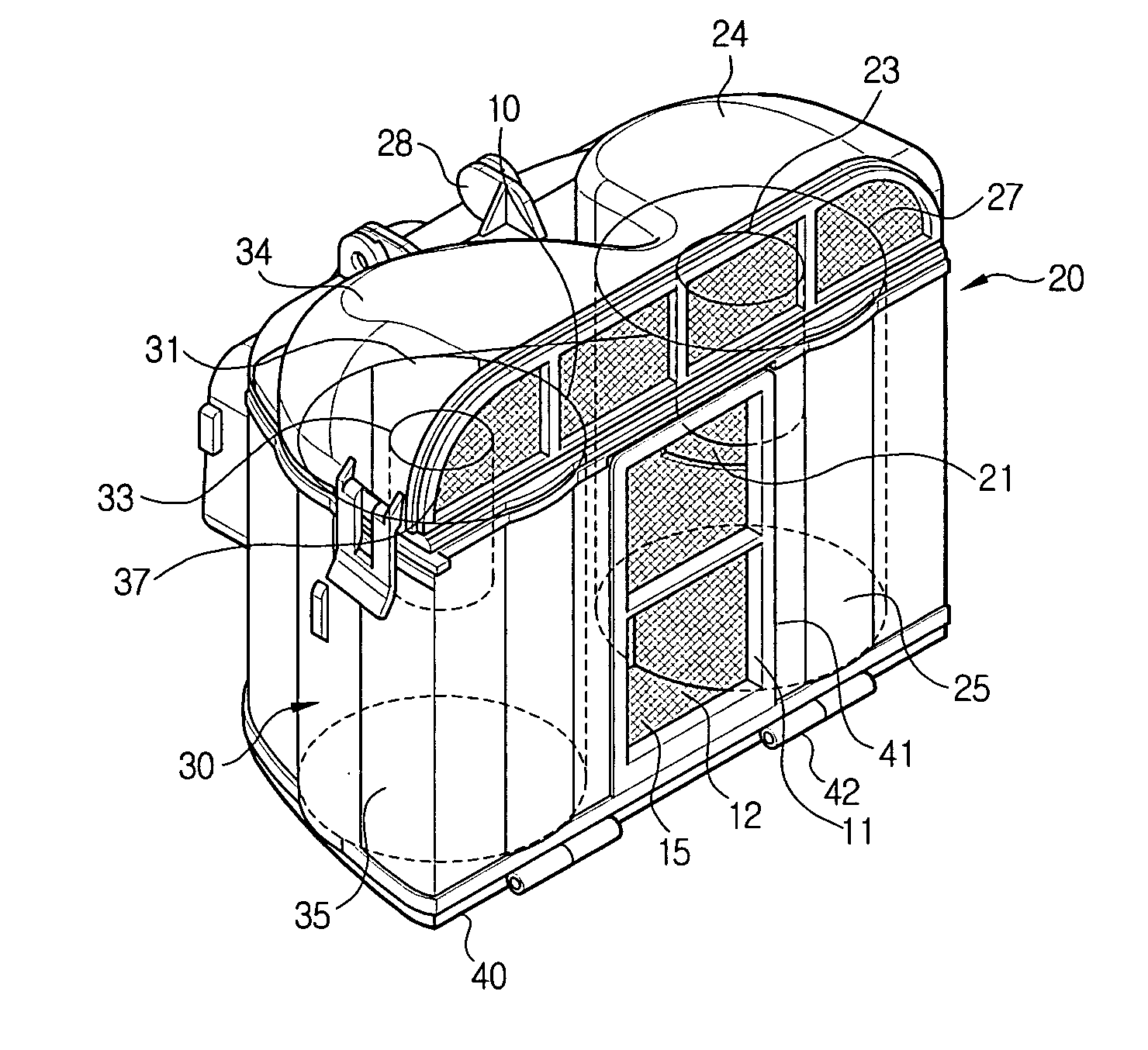
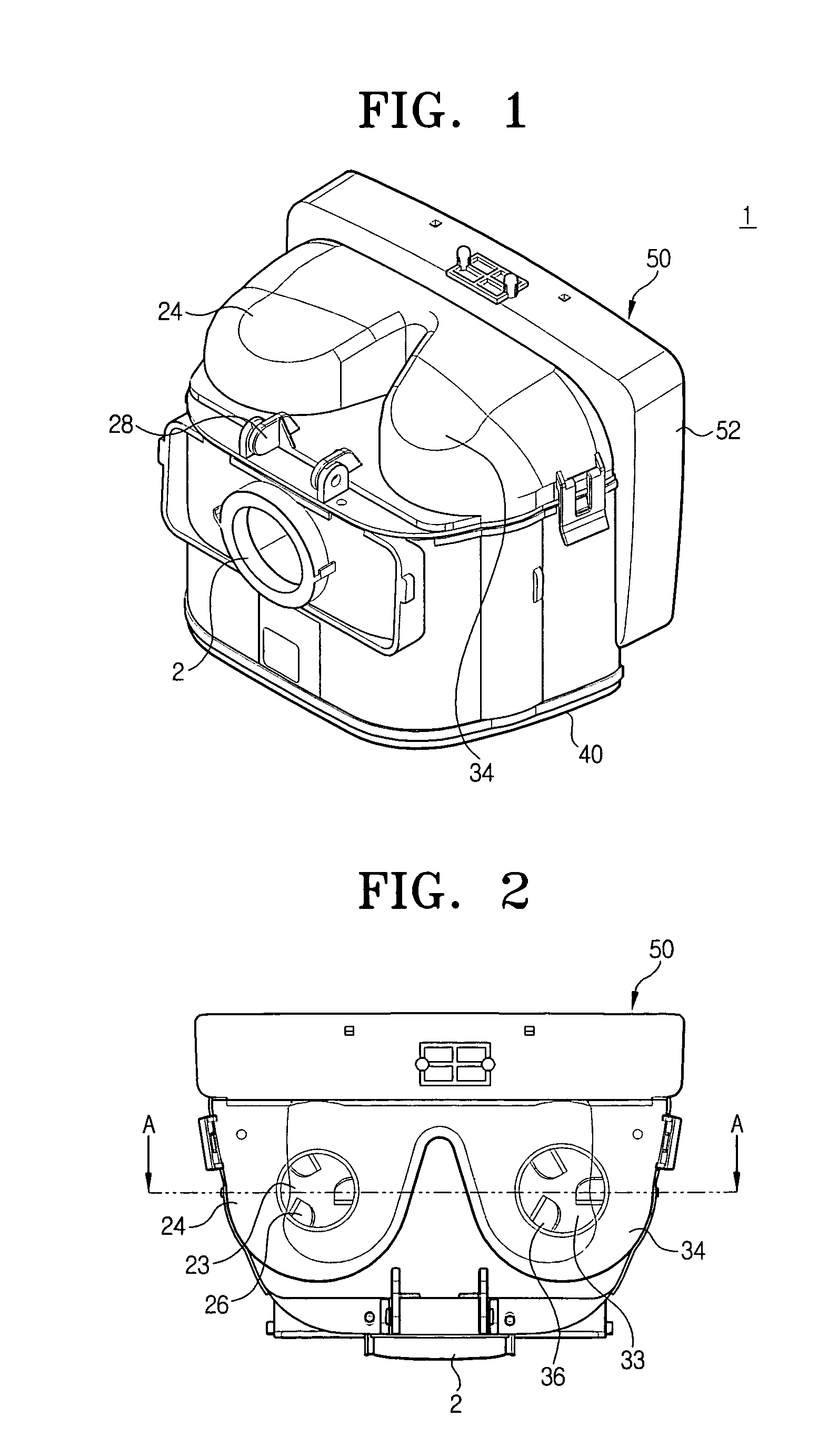
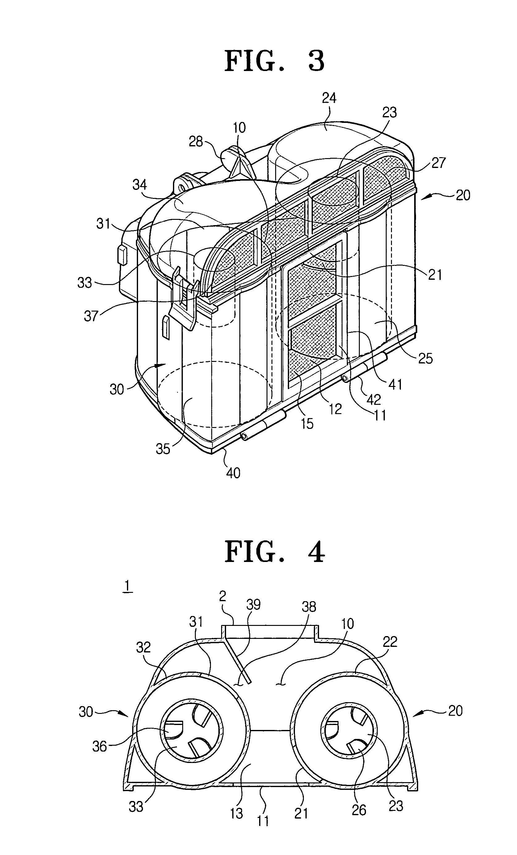
[0040]Referring to FIGS. 1 to 6, a cyclone dust separator 1 for a vacuum cleaner, according to an embodiment of the present invention, comprises a bypass path 10, a first cyclone 20, and a second cyclone 30.

[0041]The bypass path 10 guides dust-laden air drawn in through a suction opening 2 directly to a motor 133 (F...


PUM

PropertyMeasurementUnit
pressureaaaaaaaaaa
pressureaaaaaaaaaa
pressureaaaaaaaaaa

Abstract

A cyclone dust separator for a vacuum cleaner, where a couple of cyclones are disposed parallel with each other and sequentially operated to separate and collect dust. The cyclone dust separator includes a bypass path guiding dust-laden air drawn in through a suction opening directly to a motor and having a first mesh that filters off dust included in drawn-in air; a first cyclone disposed at one side of the bypass path to separate the dust from the dust-laden air drawn in through the suction opening and discharge cleaned air to the motor; and a second cyclone disposed parallel with the first cyclone to separate the dust from the dust-laden air drawn in through the suction opening and discharge cleaned air to the motor. The dust included in the air is separated sequentially by the first mesh, the first cyclone and the second cyclone.

Description

CROSS-REFERENCE TO RELATED APPLICATIONS[0001]This application claims benefit under 35 U.S.C. § 119(a) of Korean Patent Application No. 2005-32073, filed Apr. 18, 2005, the entire contents of which are incorporated herein by reference.BACKGROUND OF THE INVENTION[0002]1. Field of the Invention[0003]The present invention relates to a vacuum cleaner. More particularly, the present invention relates to a cyclone dust separator for a vacuum cleaner.[0004]2. Description of the Related Art[0005]In general, vacuum cleaners perform a cleaning work by driving a motor to generate a suction force for drawing in dust and dirt, separating and collecting the dust and dirt (hereinafter, referred to as ‘dust’) from dust-laden air using a dust separator, and discharging cleaned air.[0006]Although a variety of methods can be adopted to separate the dust, a cyclone dust separator is widely used nowadays because it is semi-permanent.[0007]The cyclone dust separator forms a whirling current with the dust-...

Claims


Application Information

Patent Timeline
Patent Type & Authority Patents(United States)
IPC IPC(8): B01D45/12B01D50/00
CPCA47L9/1641A47L9/1666B04C5/28Y10S55/03B01J8/008B01J8/02B01J2208/022
Inventor HAN, JUNG-GYUNOH, JANG-KEUN
Owner SAMSUNG GWANGJU ELECTRONICS CO LTD
Why Eureka
Try Eureka