
Brass-wind instrument valve and method

a technology for brasswind instruments and valves, applied in wind instruments, instruments, musical instruments, etc., can solve the problems of affecting the performance of brasswind instruments, and affecting the sound quality of brasswind instruments, so as to improve the acoustic characteristics of brasswind instruments, and reduce the effect of sharp bends

Inactive Publication Date: 2009-03-10
GLAZER BENOIT
View PDF4 Cites 5 Cited by
  • Summary
  • Abstract
  • Description
  • Claims
  • Application Information

AI Technical Summary

Benefits of technology

The solution enhances sound quality by reducing impedance and turbulence, resulting in improved acoustical performance with unimpeded air channels and enlarged radii, providing a more consistent and clear tone.

Problems solved by technology

The negative effects resulting from the numerous deficiencies in current brass-wind instruments have been necessary evils due to the currently widely accepted designs.
Most of the drawbacks to current brass-wind instrument sounds find their genesis in undesirable inconsistencies of the density within the concentric column of air flowing through the instrument.
There are at least three defects inherent in this design that causes impedance in the flow of the column of air traveling through the instrument leading to an interruption of the positive vortex, thereby resulting in an imperfect sound.
First, due to the distance between the valve chambers, there is a size restriction on the valve.
Because any connection of the air channels in the valve would effectively rend the instrument useless, one of the valves must have impedance.
Such impedance in the air channel operates to disrupt the positive vortices of the column of air thus negatively altering its sound.
Another defect that causes a disruption of the column of air comes as a result of the method of connecting the valve chambers to each other, as well as the remainder of the instrument.
Where two tubes are connected, often a sharp ridge or edge operates to disrupt the flow of the air column causing additional impedance in sound.
Because tubes are soldered or braised, the connection resulting from the manufacture of the instrument is often less than perfect.
This causes a negative effect on the positive vortices, thereby resulting in a diminished sound.
Additional defects inherent in the size of the valve section are the odd shapes and sharp bends of the tubes connecting the valve chambers to one another.
Odd shapes and sharp bends can hinder the desired smooth transition and impede the sound.
For example, the tuning tubes that operate to elongate the column of air often have sharp 180° bends that further impede the sound created by the player.

Method used


Image

  • Brass-wind instrument valve and method
  • Brass-wind instrument valve and method
  • Brass-wind instrument valve and method

Examples


Embodiment Construction

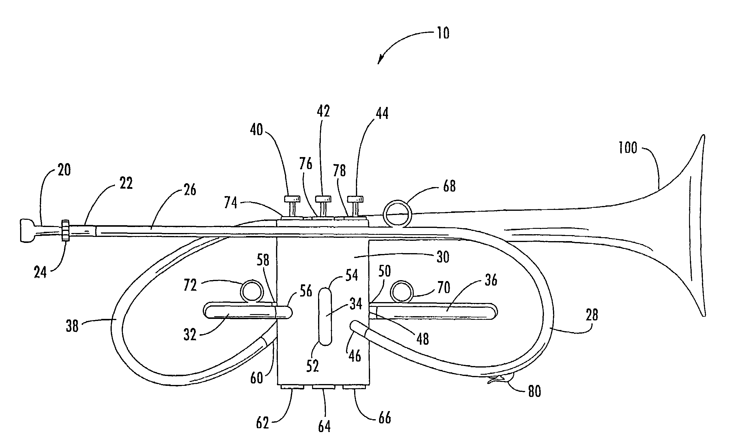
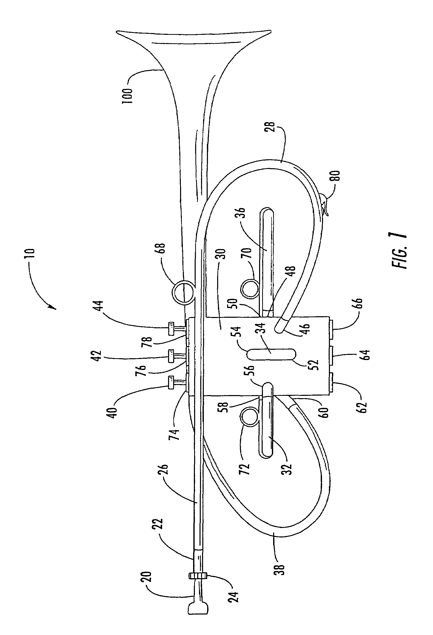
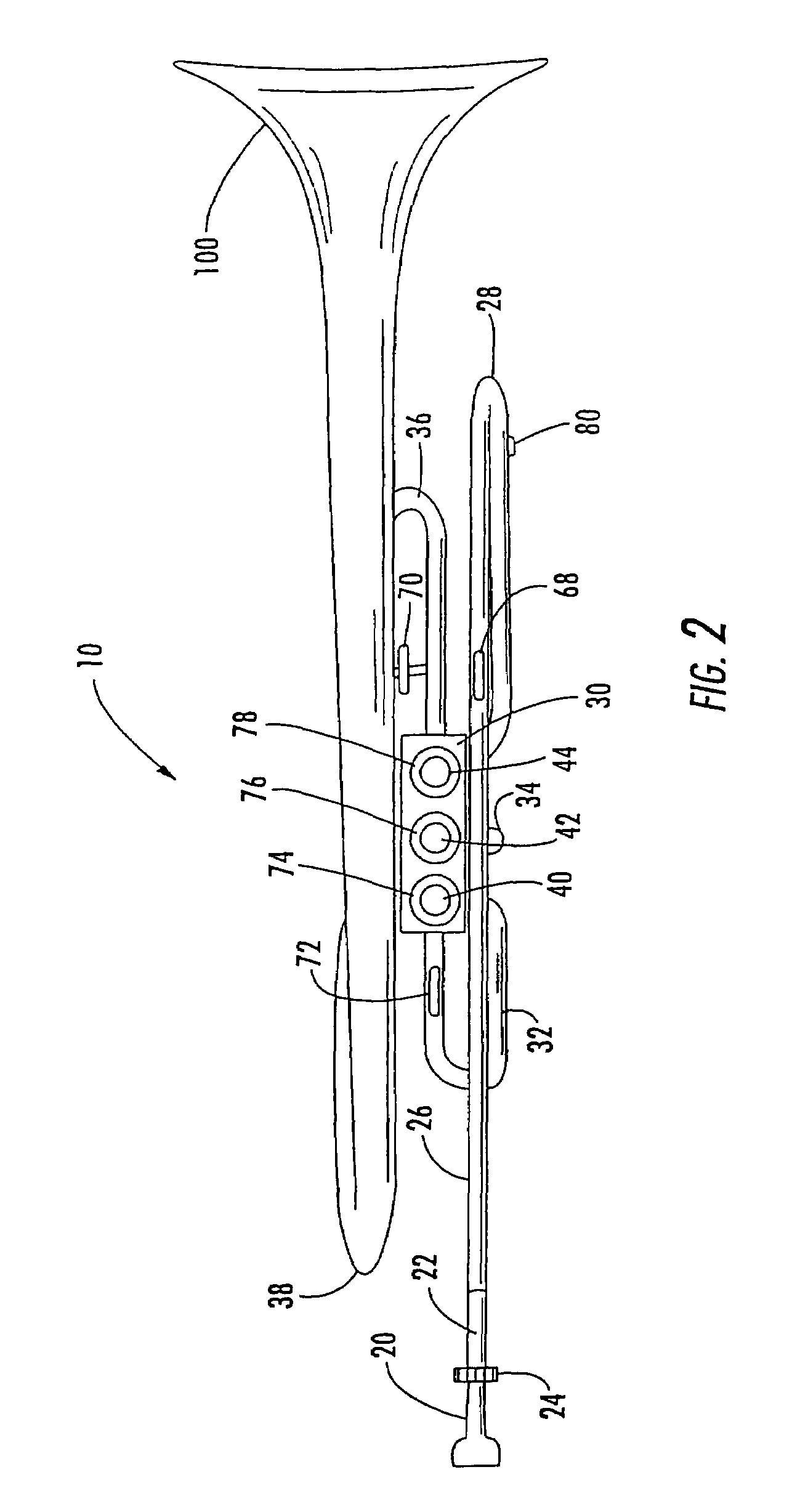
[0034]Referring now to FIGS. 1 and 2, a brass-wind apparatus comprising a monobody valve block according to the present invention is illustrated and generally referred to by the reference number 10.

[0035]The brass-wind instrument 10 generally includes a mouthpiece 20, a mouthpiece receiver 22, a lead-pipe 26, an entrance tube 28, monobody valve block 30, valves 40, 42, 44, a first-slide 32, a second-slide 34, a third-slide, 36 an exit tube, 38 and a bell 100.

[0036]Sound comprising a column of air is made at the mouthpiece 20 that is complementarily received in a mouthpiece receiver 22. The mouthpiece 20 preferably comprises a negative conical internal shape and is received in the mouthpiece receiver 22. The mouthpiece receiver 22 further comprises a friction means 24 to removably retain and adjust the mouthpiece 20 therein. The mouthpiece 20 may be adjusted to fine tune the instrument 10. The column of air is pushed from the mouthpiece 20 into the lead-pipe 26 and then into the entr...


PUM


Abstract

A brass wind instrument and method comprising: a single piece body further comprising a plurality of valve cylinders for receiving valves and a plurality of ports and interfaces in fluid communication with said valve cylinder, wherein said ports and interfaces are substantially perpendicular to the axis of said valve cylinder.

Description

FIELD OF THE INVENTION[0001]The subject invention pertains to brass-wind musical instruments and more specifically to mono body valve blocks for brass-wind instruments.BACKGROUND OF THE INVENTION[0002]In brass-wind musical instruments, sounds are initially produced by players pressing their lips against bell-shaped mouthpieces and blowing into the mouthpieces while maintaining their lips in a rigid configuration. The air passing through the rigid lips of the players causes the skin of the lip to resonate thereby resulting in a concentric column of air comprising a “buzzing” sound. As this column of buzzing air passes into the instrument, it flows through a series of tubes and valves comprising the instrument wherein it is amplified before it exits from the bell portion of the instrument thereby creating a tone. It is the series of sharp turns within the valves and tubes that generally alter the consistency of the density of the air column and have a negative effect to the tone and t...

Claims


Application Information

Patent Timeline
Patent Type & Authority Patents(United States)
IPC IPC(8): G10D7/10
CPCG10D7/10
Inventor GLAZER, BENOIT
Owner GLAZER BENOIT
Learn More