

Vehicle lamp using emitting device for suppressing color tone difference according to illumination conditions
a technology of emitting device and vehicle lamp, which is applied in the direction of discharge tube luminescnet screen, semiconductor device for light source, lighting and heating apparatus, etc., can solve the problems of pseudo lighting or non-conformity with lamp specifications, difficult to obtain light having a wide wavelength range solely from led chips, and may cause false recognition
- Summary
- Abstract
- Description
- Claims
- Application Information
AI Technical Summary
Benefits of technology
Problems solved by technology
Method used
Image

Examples
Embodiment Construction
[0024]Although the invention will be described below with reference to the exemplary embodiments thereof, the following exemplary embodiments and modifications do not restrict the invention.
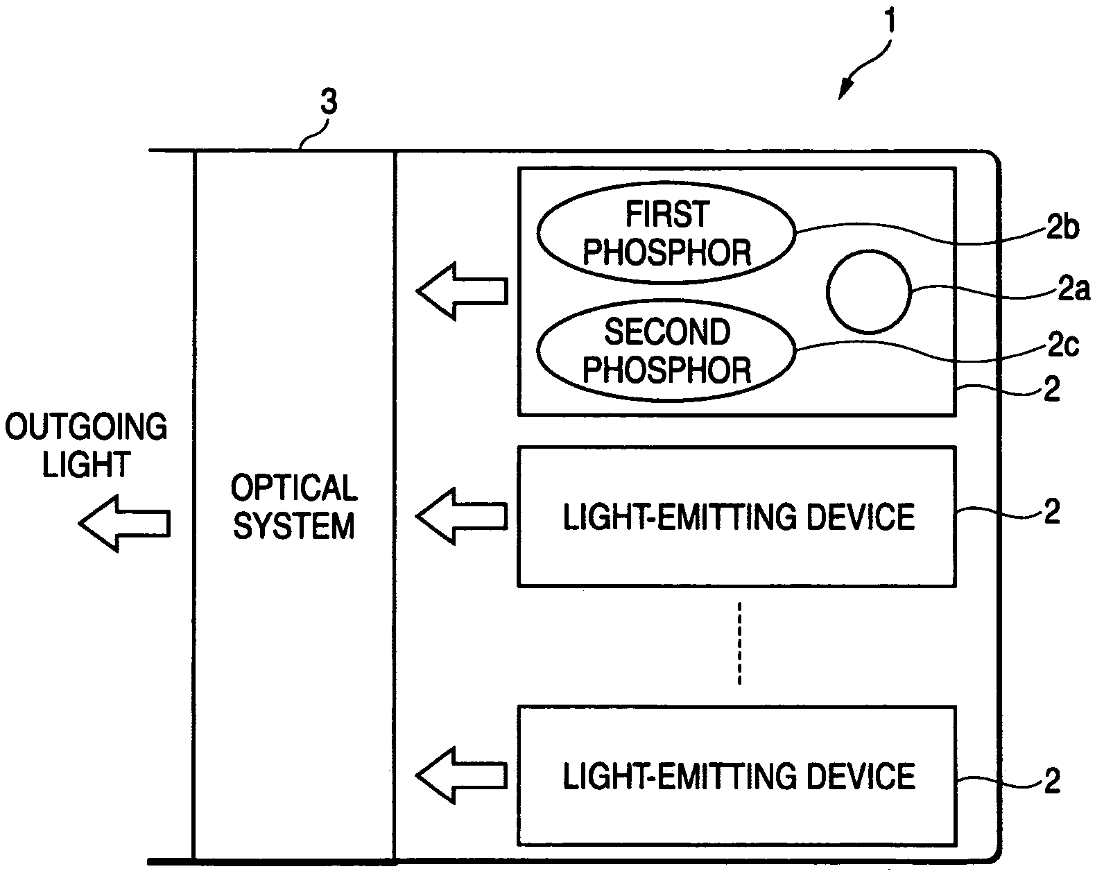
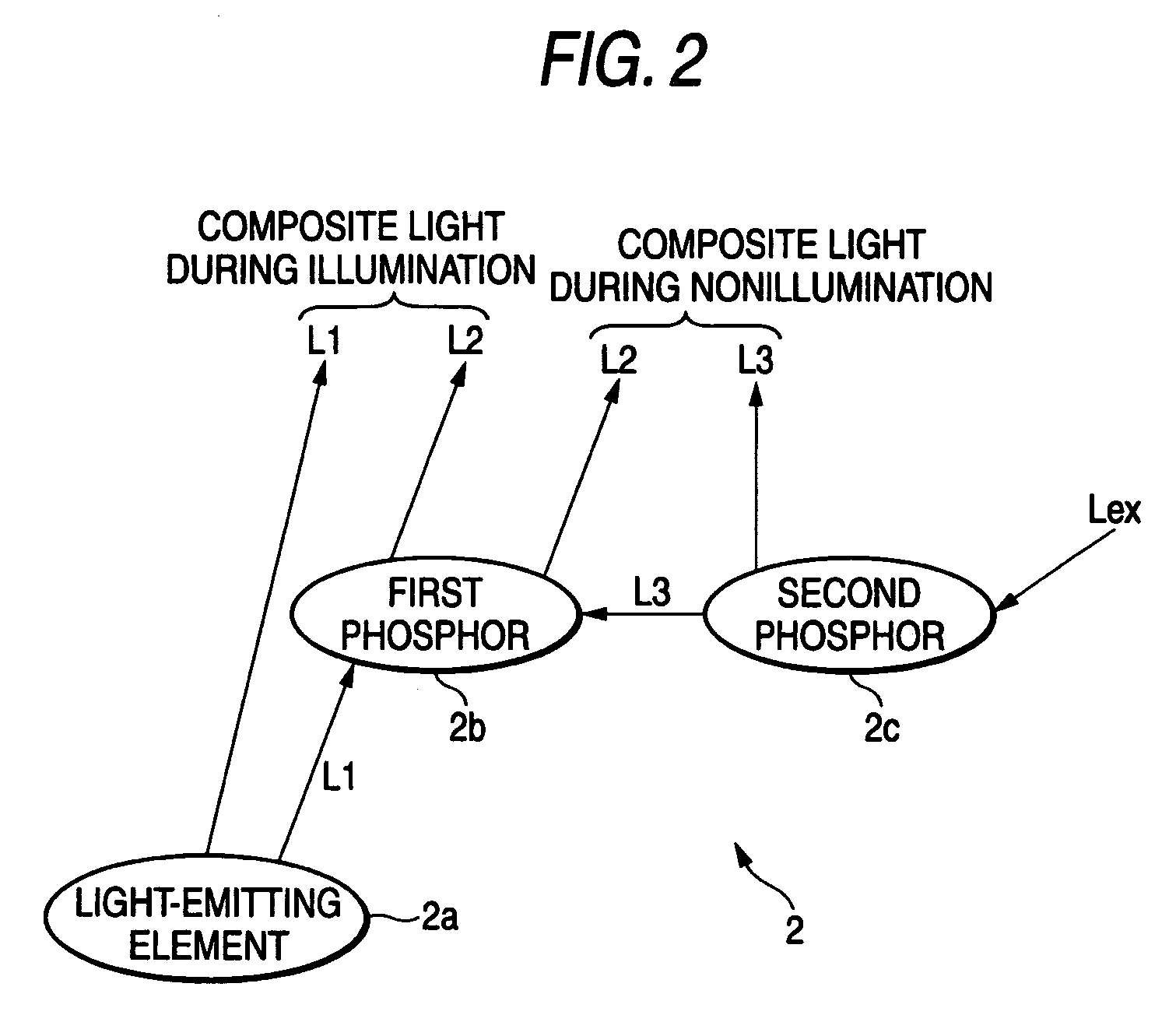
[0025]According to the exemplary embodiments, a light color of a light-emitting device during illumination can be prevented from differing from a color exhibited externally during non-illumination, thereby preventing confusion pertaining to functional colors of lamps, or the like. Specifically, when the light-emitting device is used in a vehicle lamp, influences due to reflection of a phosphor color (a color of a first phosphor) on a component (a lens, a reflection mirror, or the like) forming an optical system of a vehicle lamp can be prevented. This solves problems pertaining to conformance to lamp specifications.
[0026]For instance, in a case where the first light and the second light have wavelength ranges including blue, and the second light has a wavelength range including yellow, the extern...
PUM
 Abstract
Description
Claims
Application Information