
Surveying apparatus

a technology of a camera and a camera body, which is applied in the direction of camera, height/levelling measurement, instruments, etc., can solve the problems of difficult identification of the relative positions of features in the captured image around the measurement point, and the inability to easily determine the relative position of features in the captured imag

Active Publication Date: 2009-03-17
TAIWAN INSTR
View PDF21 Cites 57 Cited by
  • Summary
  • Abstract
  • Description
  • Claims
  • Application Information

AI Technical Summary

Benefits of technology

[0006]Therefore, an object of the present invention is to provide a surveying apparatus that captures stereo images of the area surrounding a measurement point and that is able to calculate the external orientation parameters of the stereo images.

Problems solved by technology

However, when referring to the images of a scene including the measurement point some time after the surveying, although one can determine the position of the measurement point from the measurement data, the relative positions of features in the captured image around the measurement point may not be easily determined.
In some cases, even whether or not a feature exists nearer or farther in the field than the measurement point may not be easily identified.

Method used


Image

  • Surveying apparatus
  • Surveying apparatus
  • Surveying apparatus

Examples


Embodiment Construction

[0014]The present invention is described below with reference to the embodiments shown in the drawings.

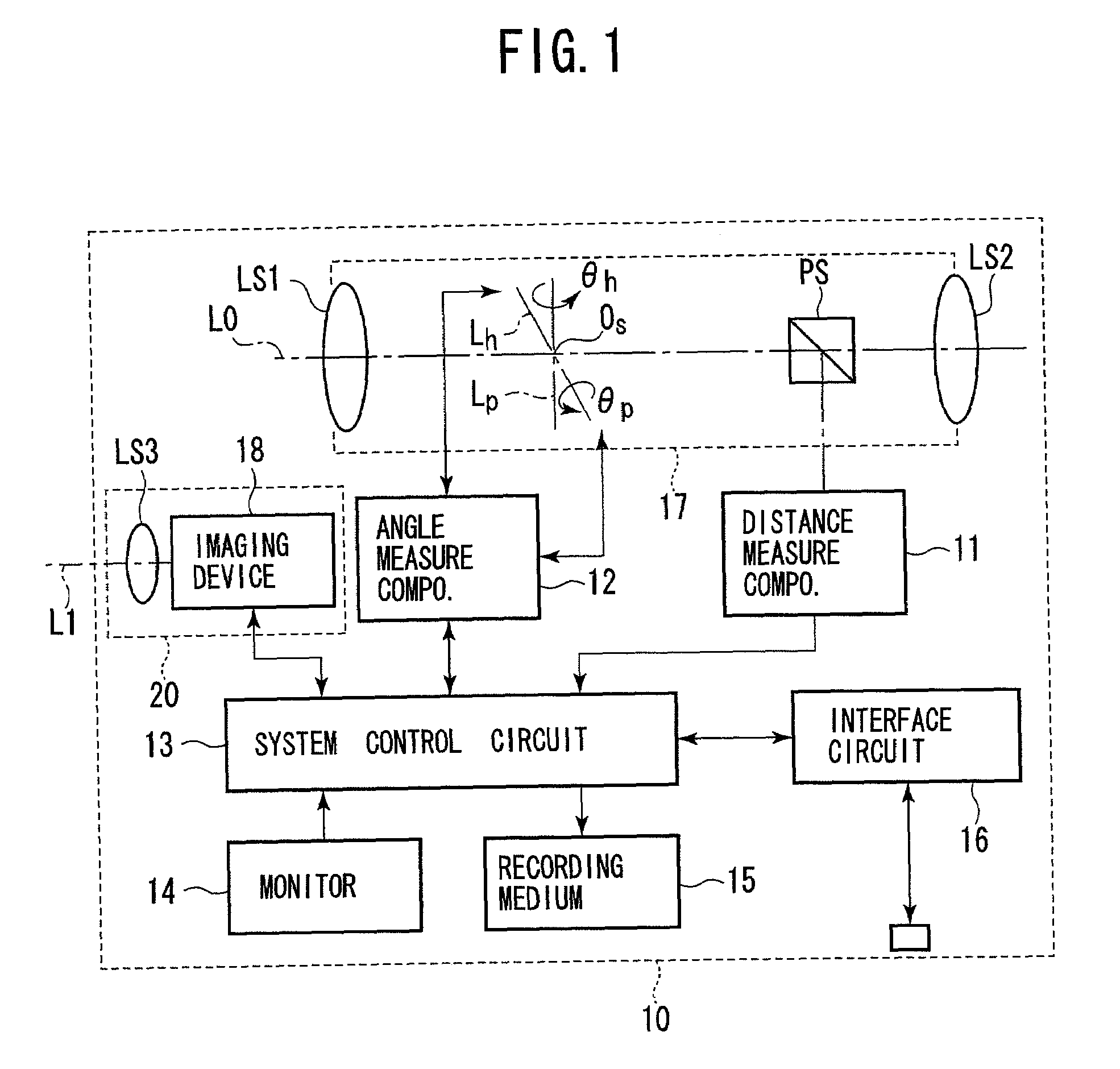
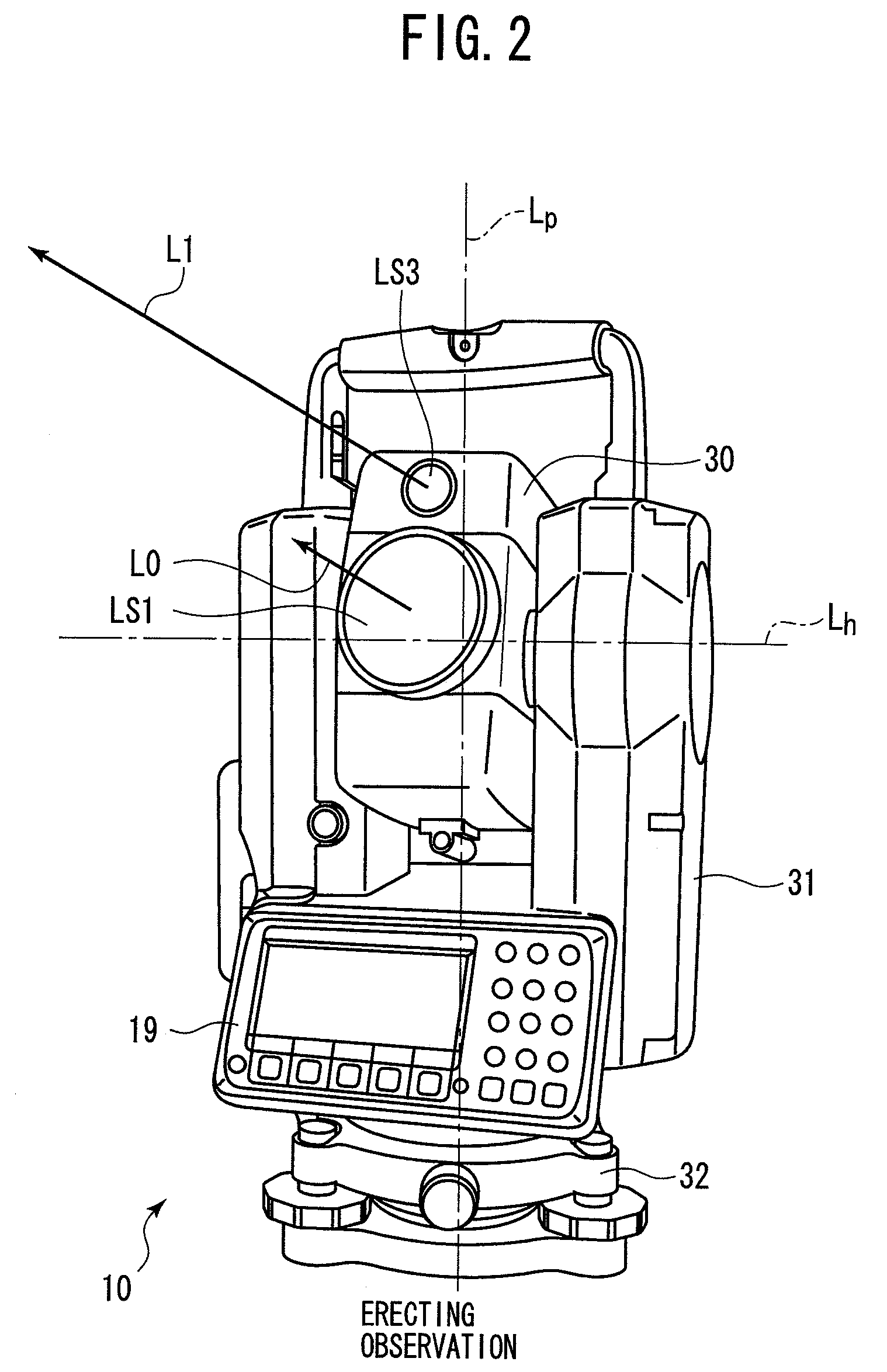
[0015]FIG. 1 is a block diagram of a surveying apparatus provided with a digital camera, to which an embodiment of the present invention is applied. FIG. 2 is a perspective view showing the appearance of the surveying apparatus of the embodiment. With reference to FIGS. 1 and 2, the structures of the surveying apparatus of the present embodiment will be described below.

[0016]The surveying apparatus 10 can be any type as long as it is rotatable by more than 180 degrees on both horizontal and perpendicular axes, such as a total station, a theodolite, etc. However, in the following descriptions, a total station will be chosen as an exemplary of the surveying apparatus 10.

[0017]The surveying apparatus 10 has a sighting telescope 17 for an operator to sight a measurement point. The sighting telescope 17 has a horizontal axis Lh for measuring a vertical angle (an altitude) θp, and a vert...


PUM


Abstract

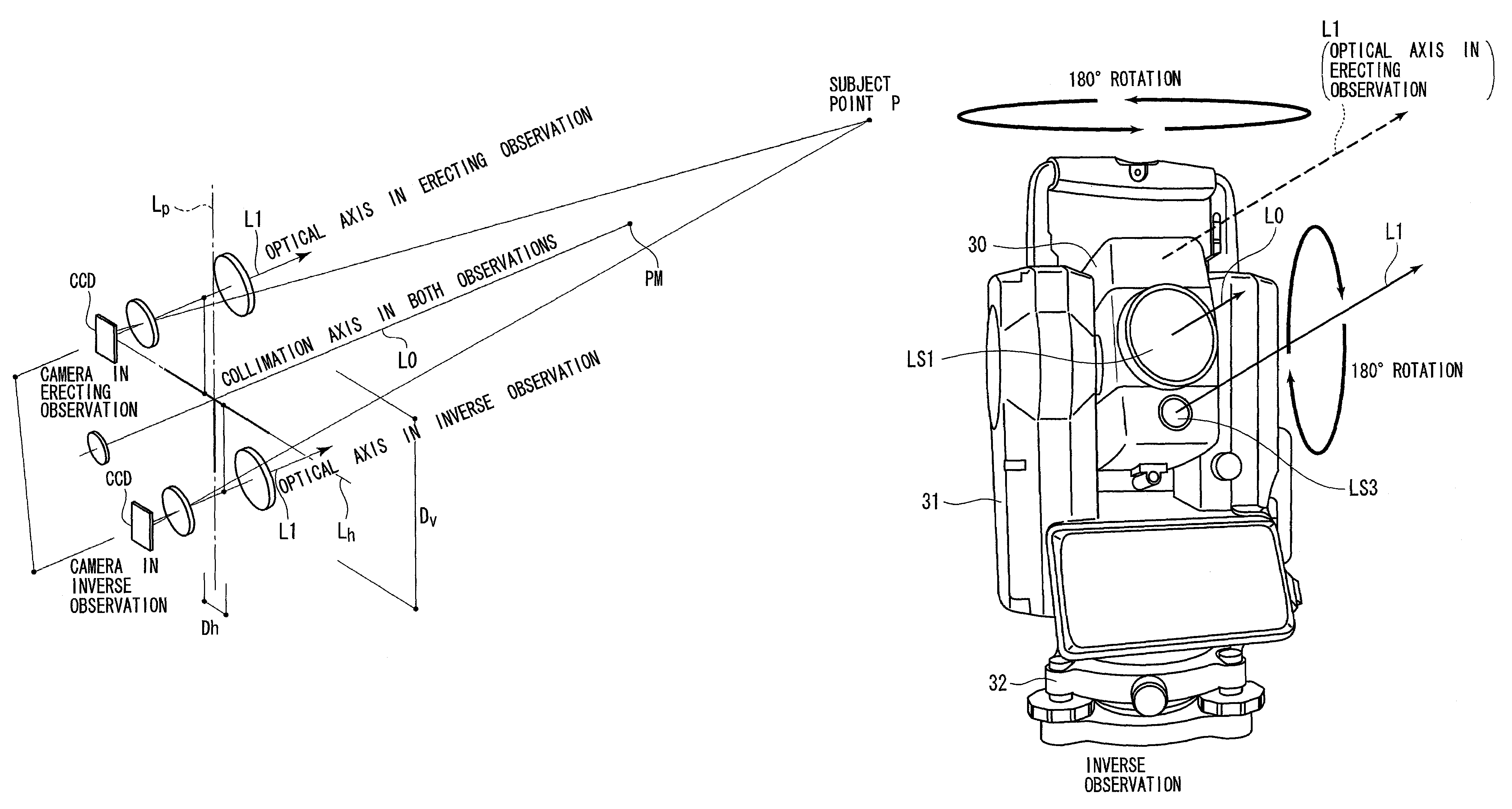
A surveying apparatus is provided that includes a sighting telescope, an imaging device, and an external orientation parameter calculator. The sighting telescope is rotatable about a horizontal axis and a vertical axis. The imaging device is integrally rotated with the sighting telescope and the imaging device has an optical axis that is different from the collimation axis. The external orientation parameter calculator calculates external orientation parameters of stereo images that are obtained by the imaging device in an erecting observation and in an inverse observation in terms of the position of the optical axis with respect to the collimation axis, and the sighting directions in the erection observation and in the inverse observation.

Description

BACKGROUND OF THE INVENTION[0001]1. Field of the Invention[0002]The present invention relates to a surveying apparatus provided with a camera for capturing an image in a surveying field.[0003]2. Description of the Related Art[0004]Conventionally, the image of an area surrounding a measurement point is often photographed and recorded with its measurement data. The image of the surveying area is generally obtained by a normal camera. Further, in Japanese Unexamined Patent Publication (KOKAI) No. 11-337336, an image including the measurement point is obtained for each measurement point by an imaging device mounted inside the surveying apparatus.SUMMARY OF THE INVENTION[0005]However, when referring to the images of a scene including the measurement point some time after the surveying, although one can determine the position of the measurement point from the measurement data, the relative positions of features in the captured image around the measurement point may not be easily determine...

Claims


Application Information

Patent Timeline
Patent Type & Authority Patents(United States)
IPC IPC(8): G01C15/00G01C1/04
CPCG01C1/04G01C15/00
Inventor MATSUO, SHUNJITAKAYAMA, HOMUYACHI, TAKANORISAKURAI, MASATOSHI
Owner TAIWAN INSTR
Learn More