Hydrostatic transaxle

a transaxle and hydrostatic technology, applied in the direction of fluid couplings, couplings, transportation and packaging, etc., can solve the problems of reducing the efficiency of vehicle manufacture, noise and shock, etc., and achieve the effect of simple and inexpensive cushion mechanism

Inactive Publication Date: 2009-03-17
KANZAKI KOKYUKOKI MFG
View PDF7 Cites 28 Cited by
  • Summary
  • Abstract
  • Description
  • Claims
  • Application Information

AI Technical Summary

Benefits of technology

[0010]Since the hydrostatic transaxle comprises the fluid-supply switching device, the hydrostatic transaxle requires no additional fluid supply device such as an exposed fluid pipe to be extended therefrom to the fluid-supply switching device, thereby reducing the number of parts and costs, and simplifying the assembling of the hydrostatic transaxle and improving the manufacture efficiency of the vehicle.
[0014]Therefore, when the vehicle travels at work or on a rough road or climbs a steep slope, the large displacement of the first hydraulic motor is selected so as to ensure slow and high-torque rotation of the first axle, and the linkage system automatically sets the fluid-supply switching device to the supply position so as to transmit the rotation force to the second axle, thereby ensuring smooth traveling of the vehicle. When the vehicle normally travels, the small displacement of the first hydraulic motor is selected so as to ensure efficient high-speed rotation of the first axle, and the linkage system automatically sets the fluid-supply switching device to the supply-stop position so as to isolate the second axle from the rotation force of the first hydraulic motor, thereby ensuring efficient fuel consumption and smooth turning of the vehicle.
[0016]Therefore, the space between the rotary shaft of the first hydraulic motor and the rotary valve serving as the fluid-supply switching device is minimized, and the linkage system is compactly disposed in this space so as to minimize the hydrostatic transaxle.
[0018]Therefore, the cushion mechanism ensures the association of the shift of the fluid-supply switching device between the supply position and the supply-stop position with the operation of the displacement control device for changing the displacement of the first hydraulic motor, even if the movable range of the displacement control device is smaller or larger than the shiftable range of the fluid-supply switching device.
[0020]Therefore, while various vehicles require various differences between the movable range of the displacement control device and the shiftable range of the fluid-supply switching device, only the link element is optionally designed so as to correspond to the difference between the movable range of the displacement control device and the shiftable range of the fluid-supply switching device in a target vehicle, whereby the linkage system having the cushion mechanism, i.e., the linkage system, which surely associates the shift of the fluid-supply switching device between the supply position and the supply-stop position with the operation of the displacement control device for changing the displacement of the first hydraulic motor, can be easily adapted for any vehicle.
[0022]Therefore, due to the elastic element, which requires no complicated design (such as to be required for the above link element for corresponding to the link ratio difference) for corresponding to the difference between the movable range of the displacement control device and the shiftable range of the fluid-supply switching device, the cushion mechanism can be simple and inexpensive.

Problems solved by technology

However, the switching of the mechanical clutch accelerates abrasion of components of the sub-transmission, and causes noise and shock.
Here, the drive-mode change valve is desired to have no exposed fluid pipe such as to complicate the assembling of the hydrostatic transaxle and to reduce efficiency of manufacture of the vehicle.

Method used


Image

  • Hydrostatic transaxle
  • Hydrostatic transaxle
  • Hydrostatic transaxle

Examples


Embodiment Construction

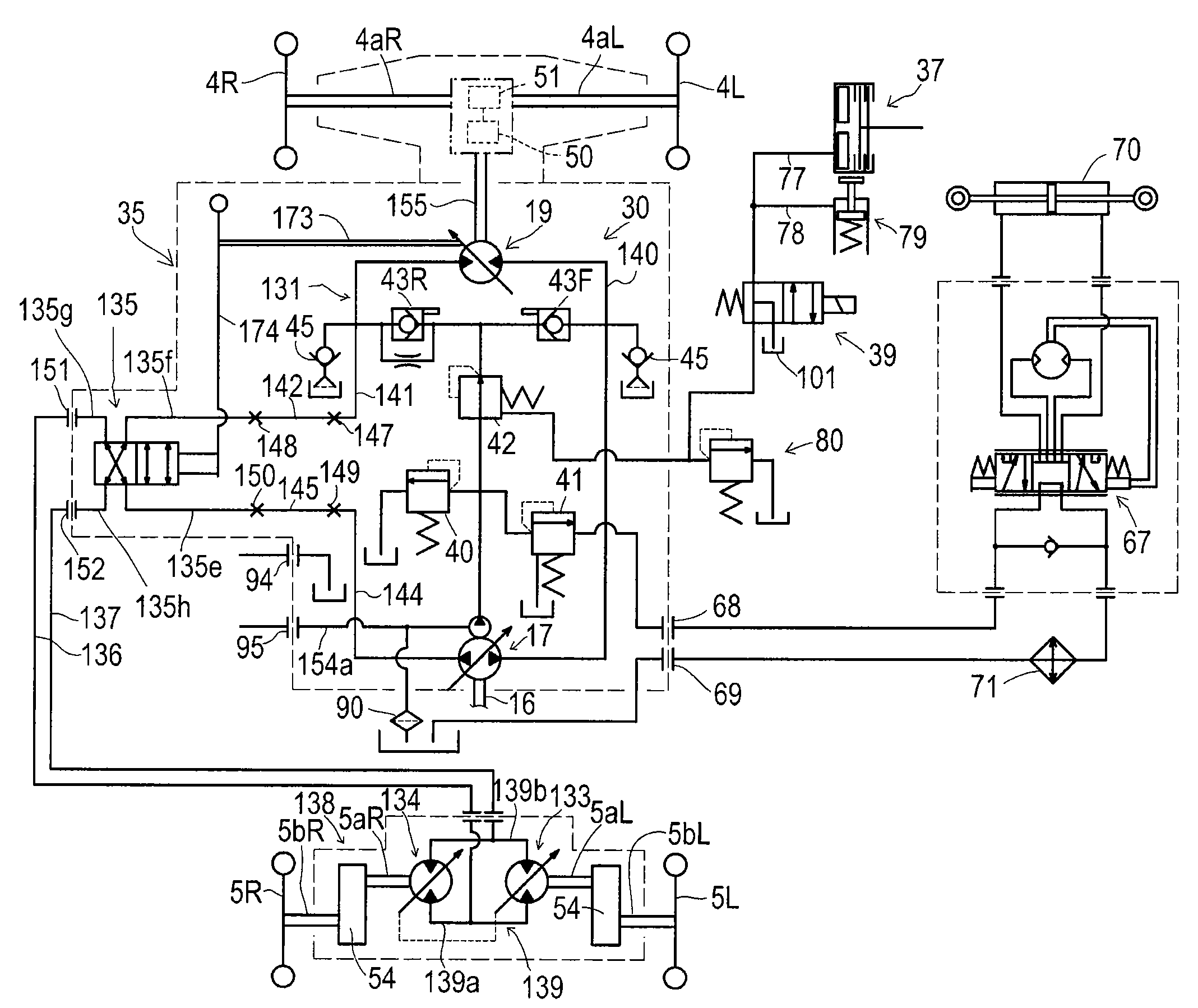
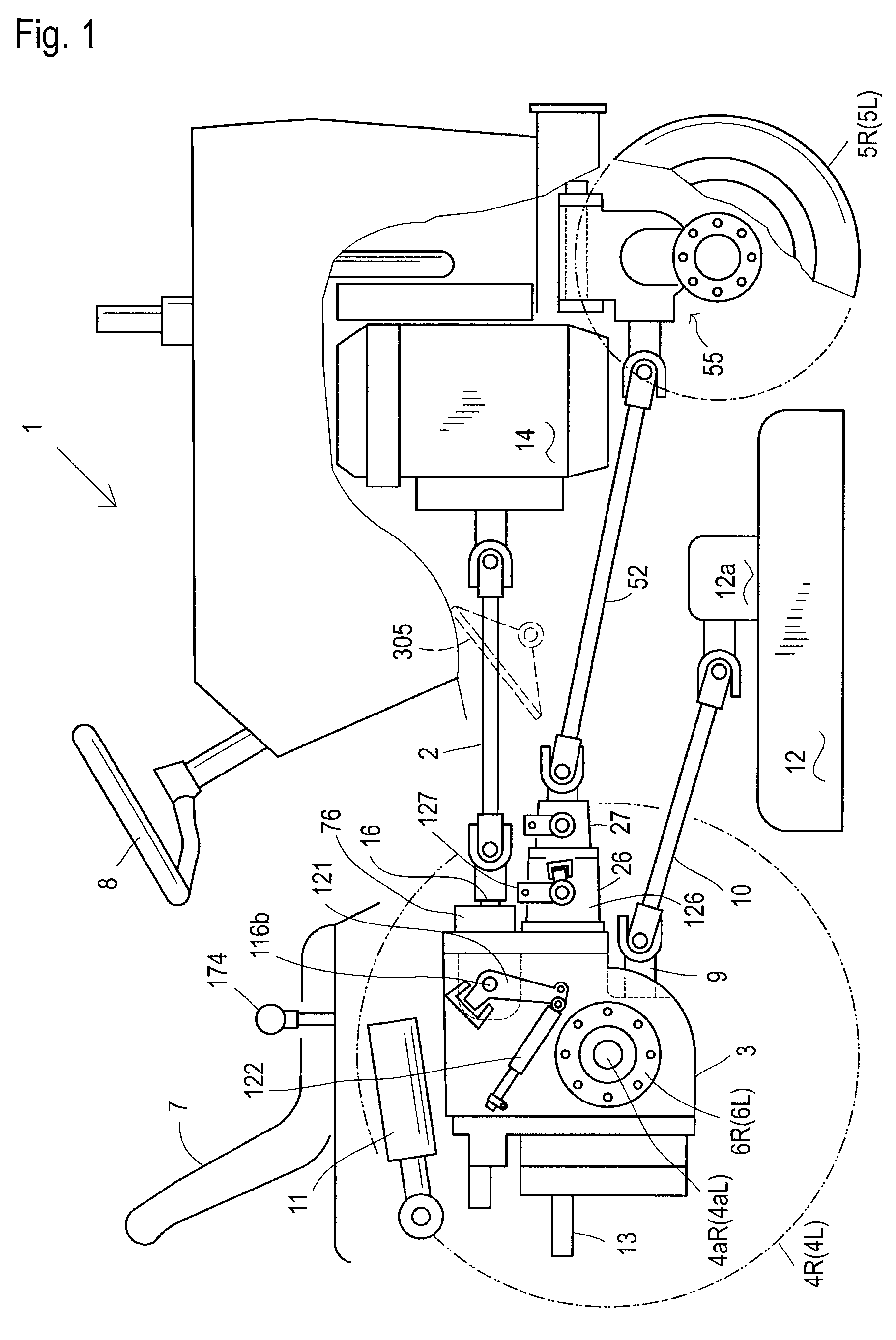
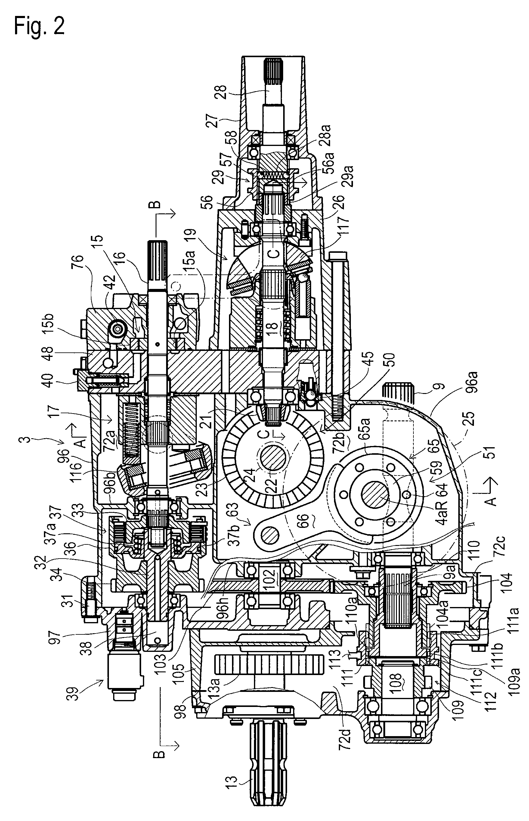
[0067]Referring to FIGS. 1 and 12, each of two different working vehicles 1 has the following common structure. Working vehicle 1 is provided at its front portion with an engine 14, and at its rear portion with a main (rear) hydrostatic transaxle 3 or 35 incorporating an HST 20 or 30. Transaxle 3 or 35 is provided with an input shaft 16, which projects forward so as to receive power from engine 14 through a propeller shaft 2 and universal joints, thereby driving HST 20 or 30 (see FIGS. 2 and 13) for driving right and left rear drive wheels 4R and 4L disposed on right and left sides of transaxle 3 or 35.

[0068]A driver's seat 7 is disposed above transaxle 3 or 35, and a steering wheel 8 is disposed in front of seat 7 so as to steer front wheels 5R and 5L for turning of vehicle 1. A sub-speed control lever 174 is disposed beside seat 7. A mid-mount mower 12 is disposed between front wheels 5R and 5L and rear wheels 4R and 4L. Transaxle 3 or 35 is provided at its lower portion with a mi...


PUM


Abstract

A hydrostatic transaxle is provided for a vehicle having a first axle and a second axle. The hydrostatic transaxle comprises: a hydraulic pump; a first hydraulic motor drivingly connected to the first axle; a closed circuit fluidly connecting the hydraulic pump to the first hydraulic motor; and a fluid-supply switching device shifted between a supply position for supplying fluid from the closed fluid circuit to a second hydraulic motor, which is disposed on the outside of the hydraulic transaxle and is drivingly connected to the second axle, and a supply-stop position for stopping the supply of fluid from the closed fluid circuit to the second hydraulic motor. The first hydraulic motor is variable in displacement, and the hydrostatic transaxle further comprises a linkage system for associating the switching of the fluid-supply switching device between the supply position and the supply-stop position with an operation for changing the displacement of the first hydraulic motor.

Description

BACKGROUND OF THE INVENTION[0001]1. Field of the Invention[0002]The present invention relates to a hydrostatic transaxle for a vehicle having first and second axles, the hydrostatic transaxle comprising: a hydraulic pump; a hydraulic motor drivingly connected to the first axle; and a closed circuit fluidly connecting the hydraulic pump to the hydraulic motor, wherein a second hydraulic motor, which is disposed on the outside of the hydrostatic transaxle and drivingly connected to the second axle, can receive power from the hydrostatic transaxle.[0003]2. Related Art[0004]Conventionally, as disclosed in JP 2002-87086 A, there is a well-known four-wheel drive vehicle equipped with a hydrostatic transaxle. The vehicle is provided with a first axle (one of front and rear axles) drivingly connected to a hydraulic motor incorporated in the hydrostatic transaxle. The vehicle is also provided with a second axle (the other of front and rear axles), which is drivingly connected to an output po...

Claims


Application Information

Patent Timeline
Patent Type & Authority Patents(United States)
IPC IPC(8): B60K17/28B60K23/08
CPCB60K17/10B60K17/356F16H61/452F16H61/44Y10T74/2186
Inventor SAKAKURA, SHINYAOKAZAKI, TAKESHIKANENOBU, HIDEKI
Owner KANZAKI KOKYUKOKI MFG
Why Eureka
Try Eureka