Dimple patterns for golf balls

a golf ball and pattern technology, applied in the field of golf ball patterns, can solve the problems of skin friction, inefficient aerodynamic shape, and difficulty in devising new symmetric patterns,

Active Publication Date: 2009-03-17
ACUSHNET CO
View PDF24 Cites 75 Cited by
  • Summary
  • Abstract
  • Description
  • Claims
  • Application Information

AI Technical Summary

Problems solved by technology

A sphere is a bluff body, which is an inefficient aerodynamic shape.
However, the penalty for reducing pressure drag is skin friction.
Because the number of symmetric solid plane systems is limited, it is difficult to devise new symmetric patterns.
Moreover, dimple patterns based some of these geometric shapes result in less than optimal surface coverage and other disadvantageous dimple arrangements.

Method used


Image

  • Dimple patterns for golf balls
  • Dimple patterns for golf balls
  • Dimple patterns for golf balls

Examples


Embodiment Construction

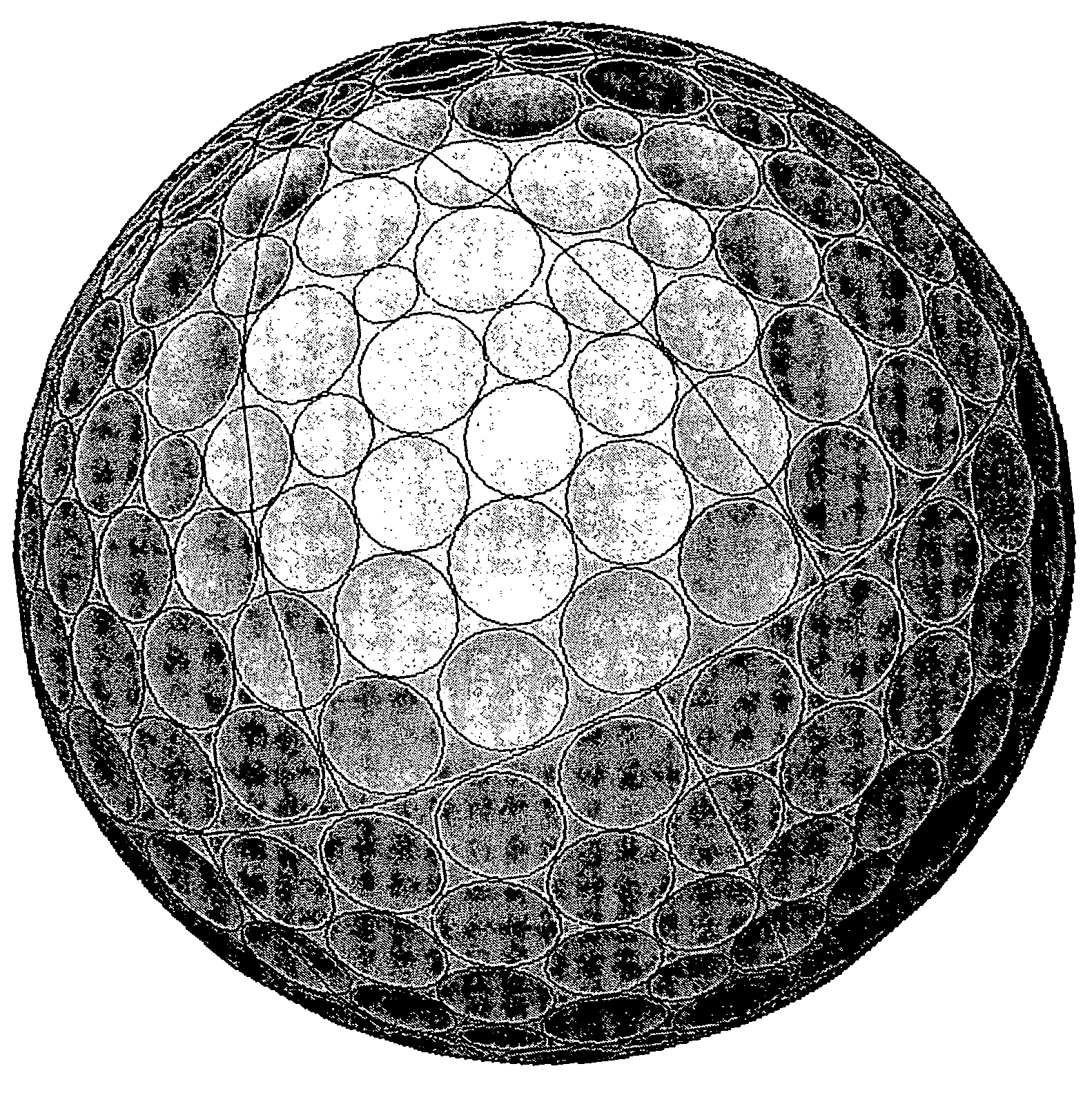
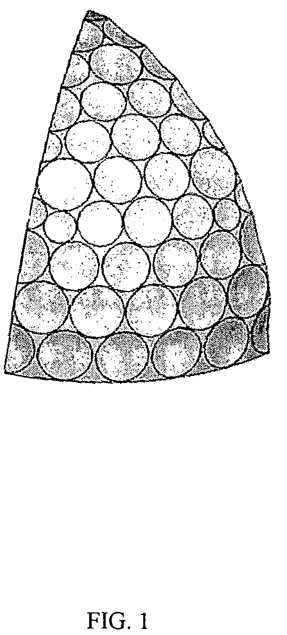
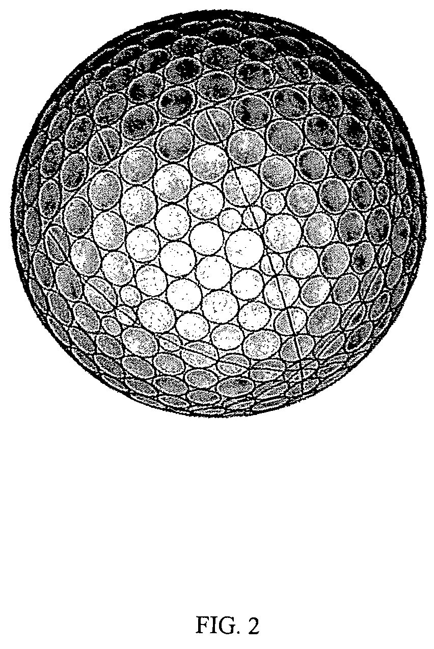
[0030]Dimple patterns may be based on polyhedra having a variety of shapes. One example of a polyhedron on which dimple patterns have been based is a hexagonal dipyramid polyhedron. Although there are some known dimple patterns based on hexagonal dipyramid polyhedra, they are unable to achieve the surface coverage disclosed by the present invention. Moreover, known dimple patterns do not have the novel dimple arrangement described below.

[0031]The present invention relates to a dimple pattern that may be used on a substantially spherical object, such as a golf ball and the like. It is desirable for the dimple pattern to be defined by, for example, a hexagonal dipyramid polyhedron. Though the present invention is discussed with respect to hexagonal dipyramid polyhedra, it will be understood that the dimple pattern of the present invention may be based on other polyhedra, geometrical shapes, or Platonic Solids known to those skilled in the art. Preferably, the dimple pattern disclosed ...


PUM


Abstract

A golf ball dimple pattern based on a hexagonal dipyramid polyhedron is disclosed. Preferably, the dimple pattern disclosed by the present invention includes dimples that are arranged such that at least a portion of neighboring dimples have one or more predetermined diameter ratios. The dimples are arranged based on six substantially similar mating dimple sections on each hemisphere. Each of the six substantially similar mating dimple sections on each hemisphere share a dimple positioned at the pole of that hemisphere. The dimple pattern is capable of achieving a surface coverage of about 82% or greater.

Description

FIELD OF THE INVENTION[0001]The present invention relates to dimple patterns that are defined by hexagonal dipyramid polyhedra. More specifically, the present invention relates to an apparatus and method for arranging dimples such that at least a portion of neighboring dimples have predetermined diameter ratios.BACKGROUND OF THE INVENTION[0002]Historically, dimple patterns for golf balls have had an enormous variety of geometric shapes, patterns, and configurations. Primarily, patterns are laid out in order to provide desired performance characteristics based on the particular ball construction, material attributes, and player characteristics influencing the ball's initial launch angle and spin conditions. Therefore, pattern development is a secondary design step that is used to achieve the appropriate aerodynamic behavior, thereby tailoring ball flight characteristics and performance.[0003]Aerodynamic forces generated by a ball in flight are a result of its velocity and spin. These...

Claims


Application Information

Patent Timeline
Patent Type & Authority Patents(United States)
IPC IPC(8): A63B37/12
CPCA63B37/0004A63B37/14A63B45/00A63B37/0006A63B37/0018A63B37/002A63B37/0021A63B37/0089A63B37/009A63B37/0096A63B37/00065
Inventor NARDACCI, NICHOLAS M.MORGAN, WILLIAM E.
Owner ACUSHNET CO
Why Eureka
Try Eureka