Multiple extruder assembly and process for continuous reactive extrusion

a technology of reactive extrusion and extruder, which is applied in the direction of application, dough shaping, sweetmeats, etc., can solve the problems of excessive shear in the polymer, increased instability of the free shaft end, and potential over-torque condition of the driven shaft end

Inactive Publication Date: 2006-04-13
ORREX PLASTICS CO LLC
View PDF13 Cites 53 Cited by
  • Summary
  • Abstract
  • Description
  • Claims
  • Application Information

AI Technical Summary

Benefits of technology

[0026] The polymer flow path is at all times in a stirred condition and contained within the walls of the extruder to allow for continuous reactive and physical processes including grafting, fuctionalization, neutralization, heating, cooling, injection, solid inclusion, pressure, vacuum and volatile removal. A particularly beneficial aspect of the multiple extruder assembly disclosed herein is that extruder screw removal for cleaning or changing may be accomplished with no additional effort than that required with conventional extruders.

Problems solved by technology

However, increasing shaft length and maintaining a constant shaft diameter produce increased instability of the free shaft ends and creates a potential over-torque condition of the driven shaft end.
Free end shaft instability requires screw designs that incorporate support of the shaft end(s) that in turn can interfere with the process design, often developing excessive shear in the polymer during the final stages of the reaction processes.
Not incorporating screw designs that account for the flexibility of the free shaft ends increases shaft wear, increases extruder barrel wear and can ultimately cause catastrophic extruder failure from torsional shaft buckling or resultant shaft torsion failure.
However, if the rpm's of the extruder are slowed to increase residence time and the feed rate is held constant, the extruder shaft torque increases.
The feed rate can be decreased to lower torque, but this leads to a proportional decrease in extruder productivity.
Reducing the extruder shaft revolutions per minute also reduces the efficiency of the dispersive and distributive mixing between the polymer and the reactive agents.
Sufficient time and energy is required for the desired reactions to proceed toward completion and to remove any un-desired by-products or un-reacted materials.
However, it is likewise well understood that heating of polymers and reactive agents also leads to many undesirable and concurrent side reactions.
The longer the polymers and reactive agents are maintained at elevated temperatures, the greater the occurrence of these un-desirable side reactions.
Increasing the reaction temperatures to accelerate the reaction and thus overcome insufficient extruder length, thus results in increased polymer degradation and side reactions that reduce final product quality.
Reducing the temperatures in the extruder to reduce the un-desirable side reactions and polymer degradation also reduces the rate of the preferred reactions and requires the reaction time to necessarily be extended.
This is an expansion of 20 mm over the length of a 4,048 mm extruder for a temperature change of 390° C. Failure to allow for this linear barrel expansion can create stresses beyond the failure point of the machine parts.
This becomes increasingly difficult for extruders of large size and machines that undergo expansion and contraction on a frequent basis.
However, this design creates a polymer flow region that is unstirred by the extruder screw flights.
The polymer adjacent to the heated pipe or hose surface is subject to increased degradation and subsequent formation of gels or large cross-linked bodies within the polymer melt.
Continued heating of sensitive polymers may eventually produce char or completely degraded polymer and thus contaminate the polymer stream.
No allowance is made for expansion of the connected extruders, and it is impossible by this method to accommodate long or heavy extruder devices.
It is also impossible by this method to quickly remove the screw assemblies from the extruder barrels, as vertical disassembly of the extruder barrels along the horizontal axis is required.
The process disclosed is physically limited by the number of sequential reactions and stripping operations that can be performed on a single extruder apparatus.

Method used


Image

  • Multiple extruder assembly and process for continuous reactive extrusion
  • Multiple extruder assembly and process for continuous reactive extrusion
  • Multiple extruder assembly and process for continuous reactive extrusion

Examples


example one

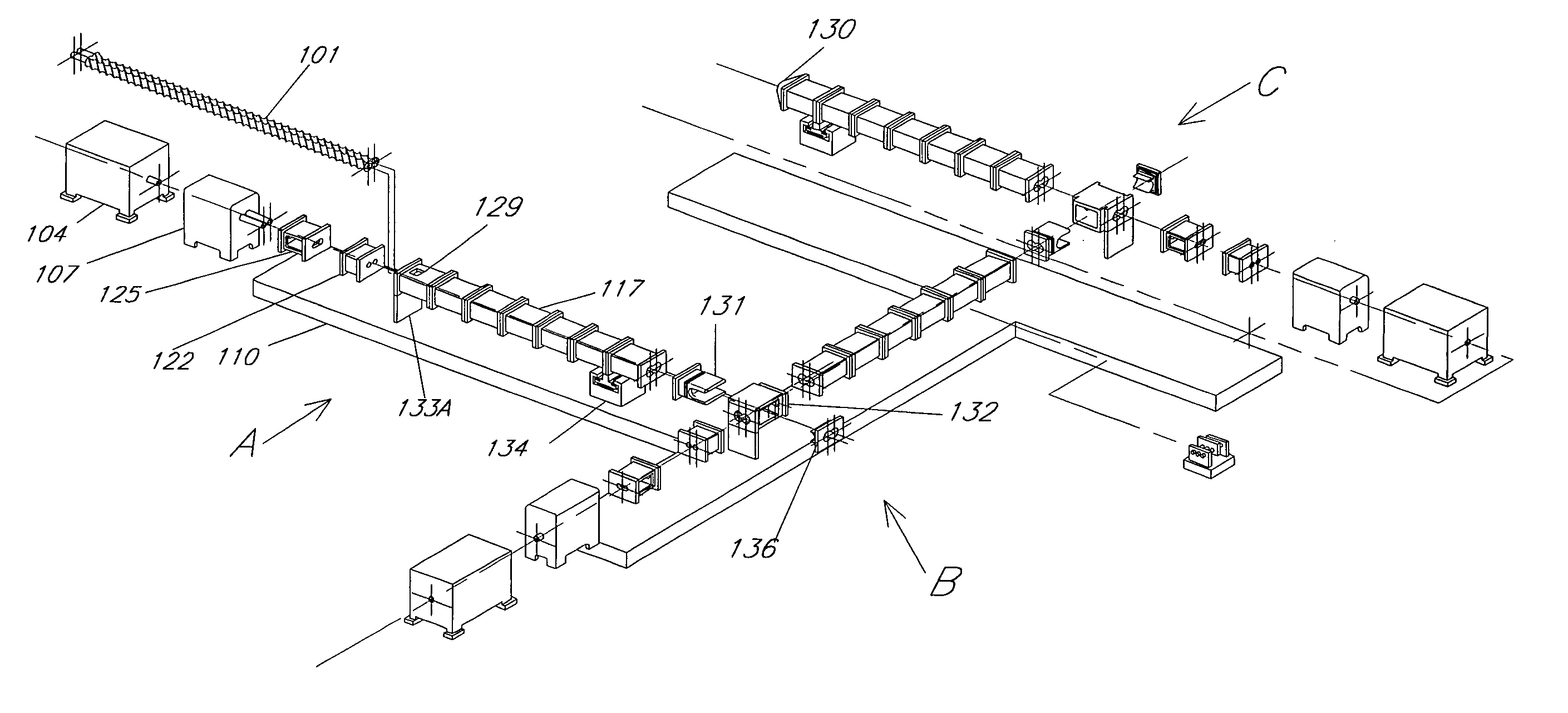
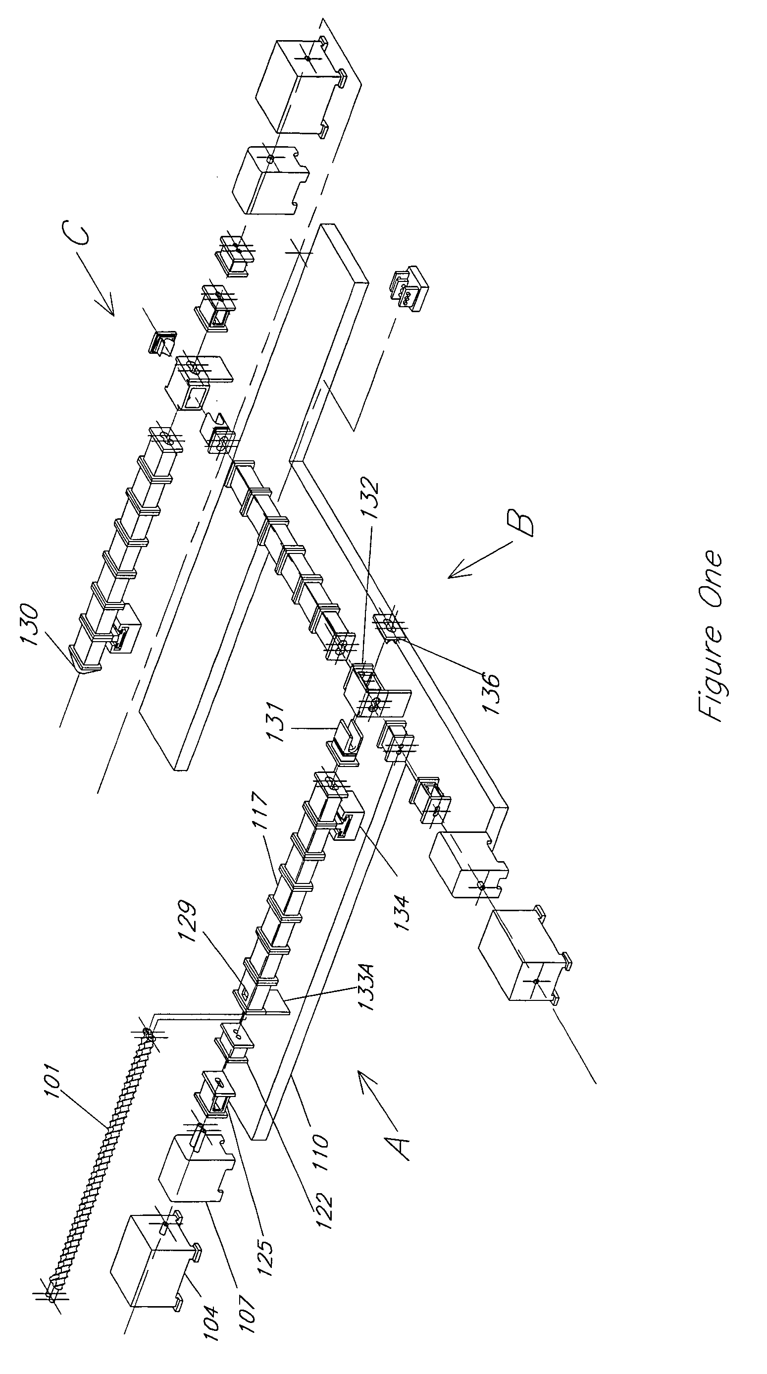
[0060] Reference is made to Figure Ten. An ethylene-propylene copolymer rubber with 49 weight % ethylene, 50 Mooney viscosity measured at 100° C. (ML 1+4) and a moisture content of less than 2.0% is ground to an average particle size of approximately 0.25″diameter and fed into the feed zone “A” of a multiple twin screw extruder assembly with total length to diameter ratio, L / D, of 88 to 1 and screw diameter of 92 mm. The feed rate is 2,000 pounds per hour. Each of the coupled extruders is powered by a 700 horsepower motor. The RPM for L / D 0 to 44 is set at 310. The RPM for L / D 45 to 88 is set at 260. The barrel temperatures in ° C. are set as indicated in Figure Ten. Vacuum is pulled from “B”, “C” and maintained at greater than 18 inches of mercury.

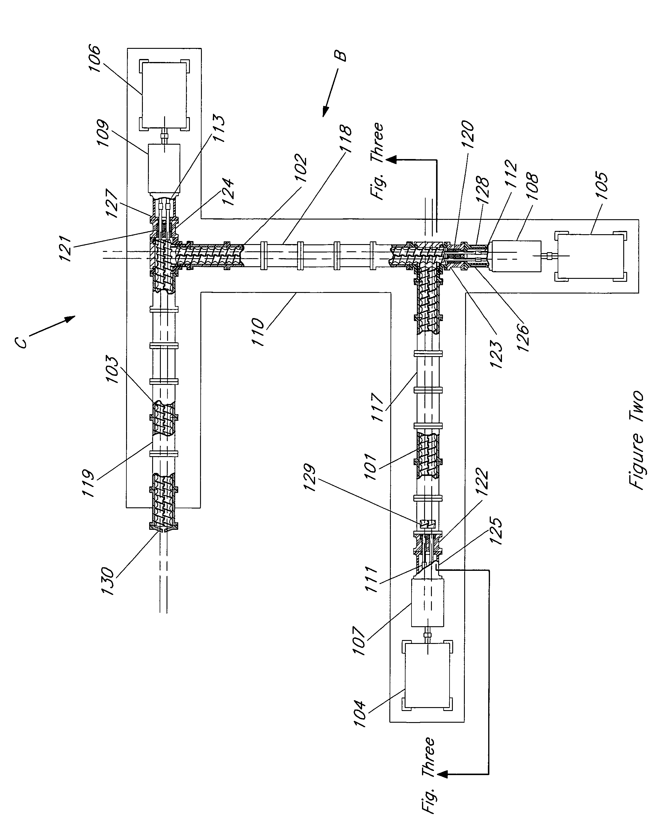
[0061] The discharge of the first extruder is fed into the second extruder that is serially connected to the first extruder with no un-mixed, uncontained or unregulated temperature zone between the two extruders. Rubber entering the seco...

example two

[0064] Reference is made to Figure Eleven. A polymer cement exiting a thin film evaporator is fed at the rate of 2,500 lbs / hr is fed into the feed zone “A” of a multiple twin screw extruder assembly with total length to diameter ratio, L / D, of 88 to 1 and screw diameter of 92 mm. Each of the coupled extruders is powered by a 700 horsepower motor. The RPM for L / D 0 to 44 is set at 150. The RPM for L / D 45 to 88 is set at 270. The barrel temperatures in ° C. are set as indicated in Figure Eleven. Vacuum is pulled from “B”, “C” and maintained at greater than 21 inches of mercury. The polymer cement feedstock has the following characteristics: weight % n-hexane=20%; weight % ethylene / propylene copolymer=80%. The ethylene / propylene copolymer has the following characteristics: weight % ethylene=49%; Mooney viscosity (ML1+4@ 1000 C)=50

[0065] The discharge of the first extruder is fed into the second extruder that is serially connected to the first extruder with no un-mixed, uncontained, or...

example three

[0069] Reference is made to Figure Twelve. The process is the same as Example 1, except the following: The product exiting the second extruder is then continuously fed into a third extruder that is serially connected to the second extruder wherein no unmixed, uncontained or temperature unregulated zone between the second and third extruders exists. The output of the second extruder is monitored by an embedded FTIR probe and control loop at location “P”. The third extruder is a 700 horsepower, 44 / 1 L / D, and 92 mm twin-screw extruder. The extruder RPM and temperatures are as shown in Figure Eleven.

[0070] Solvent neutral oil is pumped into locations “J” and “K” at the rate of 500 lbs / hr each. Molten N-phenyl para-phenylene diamine is injected in location “L” at the rate of approximately 70 lbs / hr as controlled by said FTIR probe at “P”. A vacuum of at least 24″ of mercury is pulled at location “M” to remove the water of reaction. The output of the third extruder is collected as a liqu...


PUM

PropertyMeasurementUnit
pressureaaaaaaaaaa
diameteraaaaaaaaaa
diameteraaaaaaaaaa

Abstract

Methods are disclosed for a novel and useful single pass extrusion process for the reactive extrusion and compounding of polymers. Traditional extruders utilized in reactive processes are of length to diameter ratios ranging from 30 to 1 to as high as 56 to 1. The process disclosed uses a series of sequential, very closely-coupled, independently driven screw extruders having a total effective length to diameter ratio much greater than 70 to 1 and as high as 132 to 1 or greater, and providing greatly extended reaction times, separate and multiple introductions of reactive and non-reactive agents and mechanical connections allowing for convenient screw changes and differential thermal expansion. The assembly is employed to economically produce grafted polyolefins, produce ionomers without employing the use of strong caustic agents, remove large volumes of unwanted polymer processing solvents and produce other reacted polymer species in one continuous pass.

Description

CROSS REFERENCE TO RELATED APPLICATIONS: [0001] This application claims the benefit under 35 U.S.C. 119(e) of U.S. Provisional Patent Application Ser. No. 60 / 617,548 filed Oct. 11, 2004, and entitled: “Method and Apparatus for Reactive Extrusion Using a Dual Extruder Assembly of High Effective Length-to-Diameter Ratio” the disclosure of which is hereby incorporated by reference in its entirety. This application is also related to a PCT application filed of even date herewith and entitled “Continuous Extrusion Process for Producing Grafted Polymers” by J. Nicholas Fowler, et al. The disclosure of this PCT application is also hereby incorporated by reference in its entirety.BACKGROUND OF THE INVENTION [0002] 1. Field of the Invention [0003] The present invention relates to a method and apparatus for continuously producing complex polymer compounds and reactively modified polymers in a melt phase. Compounding and reactive extrusion of polymers is a well known method for producing a wid...

Claims


Application Information

Patent Timeline
Patent Type & Authority Applications(United States)
IPC IPC(8): B29C47/38B29C47/60B29C48/03B29C48/29B29C48/295B29C48/30B29C48/38B29C48/385B29C48/395B29C48/40B29C48/76B29C48/875
CPCB29C47/0004B29C47/0009B29C47/0867B29C47/1063B29C47/50B29C47/76B29K2021/00B29K2023/00B29K2067/00B29K2075/00B29K2096/04B29K2101/12B29K2105/0005C08F8/00C08F255/00C08F10/00C08F222/00C08F220/00B29C47/004B29C47/1072B29C47/366B29C48/875B29C48/29B29C48/022B29C48/03B29C48/0011B29C48/2665B29C48/295B29C48/385B29C48/38B29C48/76B29C48/832B29C48/834B29C48/40C08F255/04
Inventor FOWLER, J. NICHOLASDECAIR, JOHN J.PHADKE, SHRIKANT V.
Owner ORREX PLASTICS CO LLC
Why Eureka
Try Eureka