Electrosurgical pencil with improved controls

a technology of electronic surgery and pencils, applied in the field of electronic surgery pencils, can solve problems such as mismatching of electrosurgical generators and electrosurgical instruments

Inactive Publication Date: 2009-03-17
COVIDIEN AG
View PDF446 Cites 94 Cited by
  • Summary
  • Abstract
  • Description
  • Claims
  • Application Information

AI Technical Summary

Benefits of technology

[0017]According to an aspect of the present disclosure an electrosurgical pencil is provided including an elongated housing; an electrocautery blade supported within the housing and extending distally from the housing, the electrocautery blade being connected to a source of electrosurgical energy; and a plurality of activation switches supported on the housing. Each activation switch is configured and adapted to selectively complete a control loop extending from the source of electrosurgical energy upon actuation thereof. In use, actuation of at least one of the plurality of activation switches produces a dividing with hemostatic effect at the electrocautery blade. The electrosurgical pencil further includes at least one voltage divider network supported on the housing. The at least one voltage divider network is electrically connected to the source of electrosurgical energy and controls the intensity of electrosurgical energy being delivered to the electrosurgical pencil.
[0023]The voltage network divider includes a slide potentiometer operatively associated with the housing. The plurality of activation switches define a first resistor network disposed within the housing. The slide potentiometer defines a second resistor network disposed within the housing. The slide potentiometer simultaneously controls the intensity of electrosurgical energy delivered to the plurality of activation switches.
[0025]A first activation switch may deliver a first characteristic signal to the source of electrosurgical energy which, in turn, transmits a waveform duty cycle which produces a cutting effect. A second activation switch may deliver a second characteristic signal to the source of electrosurgical energy which, in turn, transmits a waveform duty cycle which produces a dividing with hemostatic effect. A third activation switch may deliver a third characteristic signal to the source of electrosurgical energy which, in turn, transmits a waveform duty cycle which produces a coagulating effect.
[0027]The electrosurgical pencil further includes a molded hand grip operatively supported on the housing. The hand grip is shaped and dimensioned to reduce fatigue on the hand of the user.

Problems solved by technology

However, so many options also tend to complicate simple surgical procedures and may lead to confusion.
Due to the variety of operative, electrosurgical procedures, requiring various levels of radio frequency energy delivery from an attached instrument, issues arise with the mismatching of electrosurgical instruments and electrosurgical generators.

Method used


Image

  • Electrosurgical pencil with improved controls
  • Electrosurgical pencil with improved controls
  • Electrosurgical pencil with improved controls

Examples


Embodiment Construction

[0065]Preferred embodiments of the presently disclosed electrosurgical pencil will now be described in detail with reference to the drawing figures wherein like reference numerals identify similar or identical elements. As used herein, the term “distal” refers to that portion which is further from the user while the term “proximal” refers to that portion which is closer to the user or surgeon.

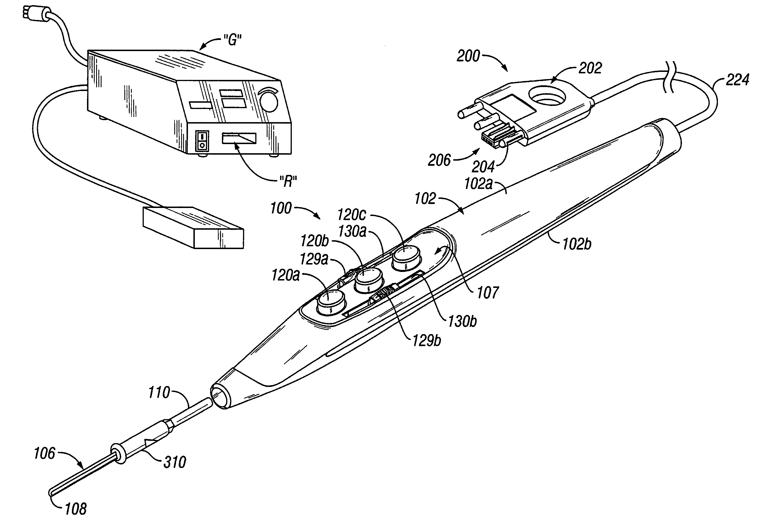
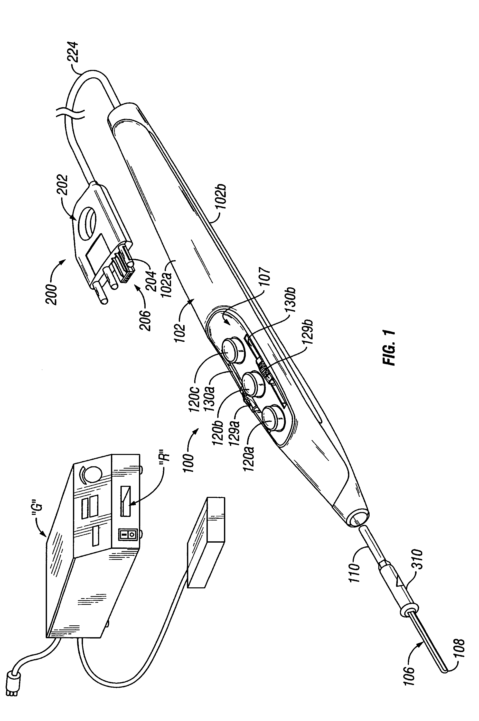
[0066]FIG. 1 sets forth a perspective view of an electrosurgical system including an electrosurgical pencil 100 constructed in accordance with one embodiment of the present disclosure. While the following description will be directed towards electrosurgical pencils it is envisioned that the features and concepts (or portions thereof) of the present disclosure can be applied to any electrosurgical type instrument, e.g., forceps, suction coagulators, vessel sealers, wands, etc.

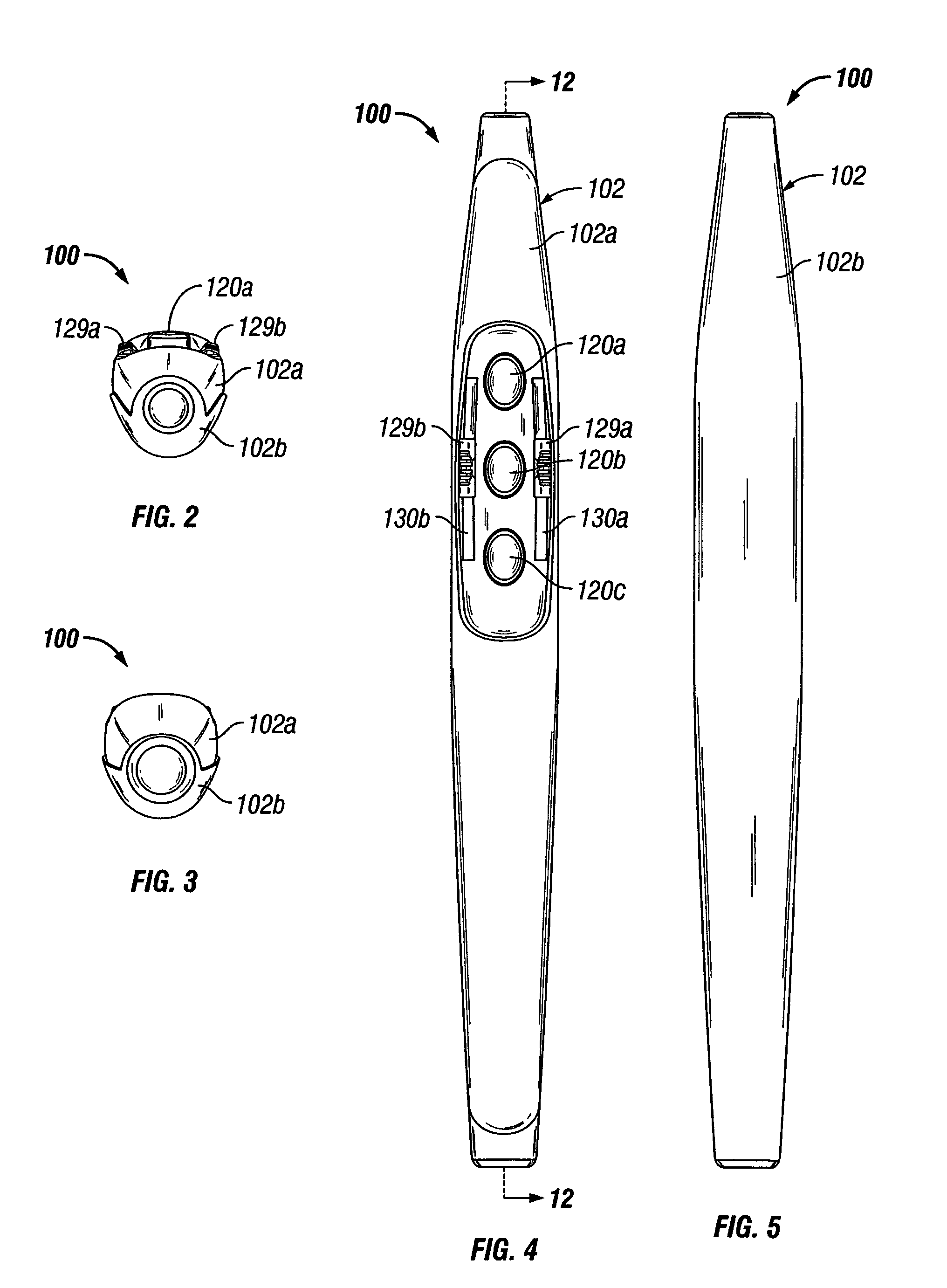
[0067]As seen in FIGS. 1-7, electrosurgical pencil 100 includes an elongated housing 102 having a top-half shell portion ...


PUM


Abstract

An electrosurgical pencil is provided and includes an elongated housing having an electrocautery blade supported therein and extending distally from the housing. The electrocautery blade is connected to a source of electrosurgical energy. The pencil further includes a plurality of activation switches supported on the housing for activating electrocautery blade. Each activation switch is configured and adapted to selectively complete a control loop extending from the source of electrosurgical energy upon actuation thereof. In use, actuation of at least one of the plurality of activation switches produces a dividing with hemostatic effect at the electrocautery blade. The electrosurgical pencil further includes at least one voltage divider network supported on the housing. The at least one voltage divider network is electrically connected to the source of electrosurgical energy and controls the intensity of electrosurgical energy being delivered to the electrosurgical pencil.

Description

CROSS-REFERENCE TO RELATED APPLICATIONS[0001]The present application claims the benefit of and priority to U.S. Provisional Application Ser. No. 60 / 666,828, filed Mar. 31, 2005, the entire contents of both of which are incorporated herein by reference.[0002]The present application is also a Continuation-in-Part Application which claims the benefit of and priority to Continuation-in-Part application Ser. No. 10 / 959,824, filed on Oct. 6, 2004, now U.S. Pat. No. 7,156,842, which in turn claims the benefit of and priority to International Application No. PCT / US03 / 37111, filed on Nov. 20, 2003, the entire contents of both of which are incorporated herein by reference.BACKGROUND[0003]1. Technical Field[0004]The present disclosure relates generally to electrosurgical instruments and, more particularly, to an electrosurgical pencil having a plurality of hand-accessible variable controls.[0005]2. Background of Related Art[0006]Electrosurgical instruments have become widely used by surgeons i...

Claims


Application Information

Patent Timeline
Patent Type & Authority Patents(United States)
IPC IPC(8): A61B18/18
CPCA61B18/1402A61B2018/00928A61B2018/00946
Inventor SARTOR, JOE DONEHR, CHRIS J.RESCHKE, ARLEN J.
Owner COVIDIEN AG
Why Eureka
Try Eureka