Battery test module

a battery test and module technology, applied in the field of storage batteries, can solve the problems of determining bad batteries and prior art lacked a simple technique for testing storage batteries without relying on separate testing equipmen

Inactive Publication Date: 2009-03-17
MIDTRONICS
View PDF456 Cites 85 Cited by
  • Summary
  • Abstract
  • Description
  • Claims
  • Application Information

AI Technical Summary

Problems solved by technology

If the voltage is below a certain threshold, the battery is determined to be bad.
The prior art has lacked a simple technique for the testing of a storage battery without relying on separate testing equipment.

Method used


Image

  • Battery test module
  • Battery test module
  • Battery test module

Examples


Embodiment Construction

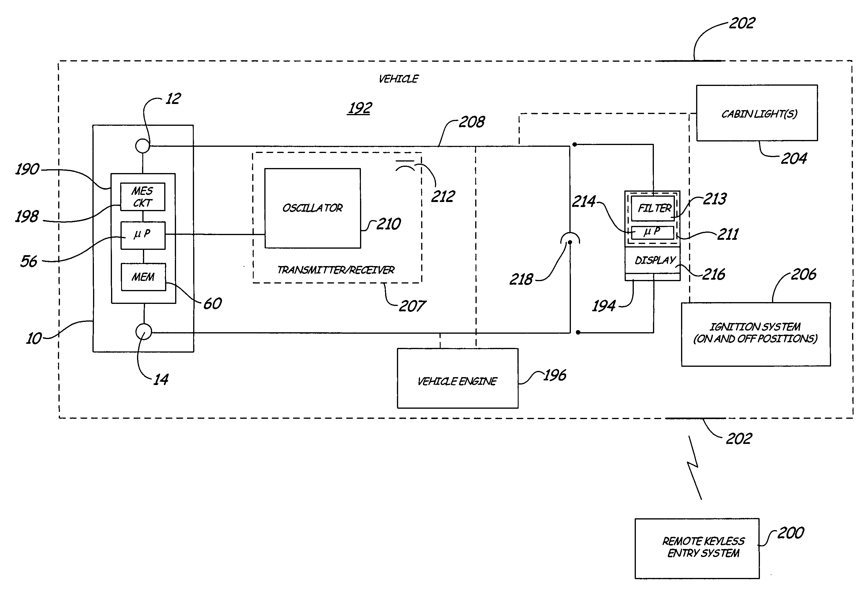
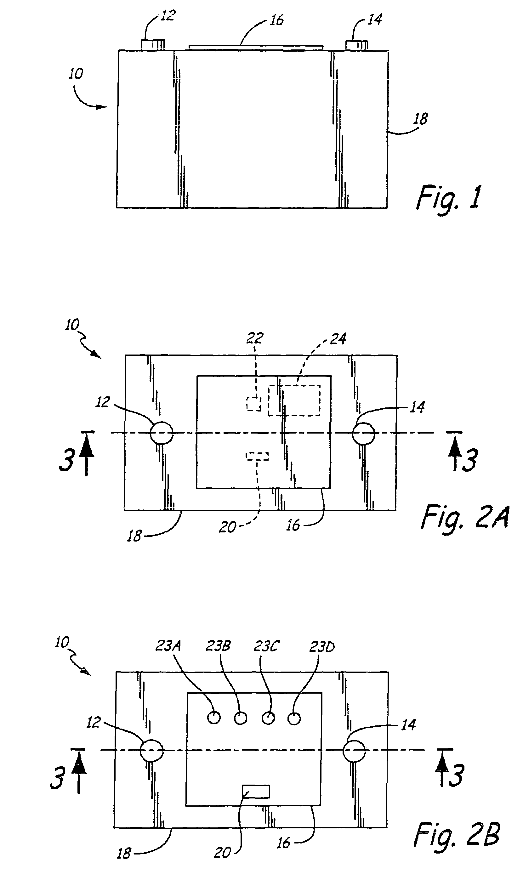
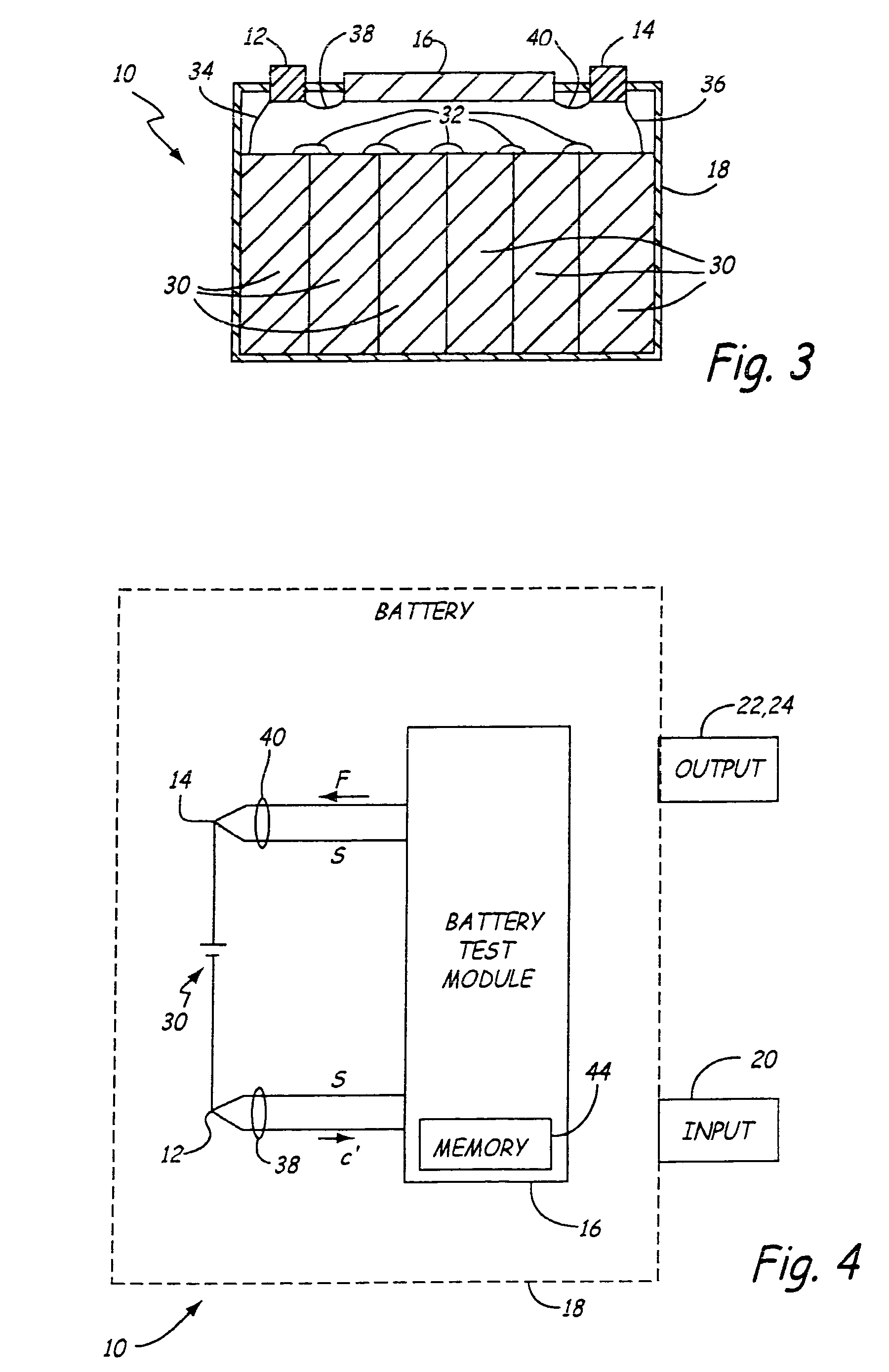
[0026]In one aspect of the present invention a storage battery is provided having an integrated battery test module for performing a battery test on electrical cells of the storage battery. As used herein “integrated” can include a separate module which is attached to the battery housing. In one embodiment, the battery test module is electrically coupled to the electrical cells of the storage battery through Kelvin connections. In certain aspects, Kelvin connections are not used. As the battery test module is integral with the battery, an operator can test the battery without relying on external battery test equipment. In one embodiment, the battery test is one that can be easily performed by an unskilled operator. The battery test module is preferably manufactured using low cost techniques which may be integrated with a storage battery without an excessive increase in the cost to produce the battery. Further, the battery test module is capable of outputting battery condition inform...


PUM

PropertyMeasurementUnit
voltage potentialaaaaaaaaaa
total voltageaaaaaaaaaa
voltagesaaaaaaaaaa

Abstract

A storage battery includes a battery housing and a plurality of electrochemical cells in the battery housing electrically connected to terminals of the battery. A battery test module is mounted to the battery housing and electrically coupled to the terminals through Kelvin connections. A display or other output is configured to output battery condition information from the battery test module. The battery test module is configured to automatically carry out a battery test when a voltage across the battery falls below a predetermined threshold.

Description

CROSS REFERENCE TO RELATED APPLICATIONS[0001]The present application claims the benefit of U.S. provisional patent application Ser. No. 60 / 577,345, filed Jun. 4, 2004 and is a Continuation-In-Part of U.S. patent application Ser. No. 10 / 310,515, filed Dec. 5, 2002 which claims the benefit of U.S. provisional patent application Ser. No. 60 / 341,902, filed Dec. 19, 2001 and is a Continuation-In-Part of U.S. patent application Ser. No. 10 / 217,913, filed Aug. 13, 2002 which is a Continuation-In-Part of U.S. patent application Ser. No. 09 / 880,473, filed Jun. 13, 2001 which is a Continuation-In-Part of and claims priority of U.S. patent application Ser. No. 09 / 780,146, filed Feb. 9, 2001 which is based on and claims the benefit of U.S. provisional patent application Ser. No. 60 / 181,854, filed Feb. 11, 2000; U.S. Provisional patent application Ser. No. 60 / 204,345, filed May 15, 2000; U.S. provisional patent application Ser. No. 60 / 218,878, filed Jul. 18, 2000; and U.S. provisional patent app...

Claims


Application Information

Patent Timeline
Patent Type & Authority Patents(United States)
IPC IPC(8): G01R31/36G01N27/416G01R1/20
CPCG01R19/16542G01R31/3648G01R31/3631G01R31/3696G01R31/386G01R31/364
Inventor RESTAINO, HARVEY A.BUTTERIS, JAMEY L.
Owner MIDTRONICS
Why Eureka
Try Eureka