Shift register

a technology of shift register and shift register, applied in the field of shift register, can solve the problems of additional electricity consumption and additional electricity consumption, and achieve the effect of reducing electricity consumption

Inactive Publication Date: 2009-03-24
CHUNGHWA PICTURE TUBES LTD
View PDF9 Cites 2 Cited by
  • Summary
  • Abstract
  • Description
  • Claims
  • Application Information

AI Technical Summary

Benefits of technology

[0010]The object of the present invention is to provide a shift register with lower electricity consumption.
[0016]According to the preferred embodiments of the present invention, the internal signals of the stage circuit are used to produce the control signals, so as to replace a part of the clock signals required during the operation of the same stage circuit in the present invention. Therefore, both the unstable state caused by the coupling of the external clock signals and the undesirable high-frequency clock signal oscillation can be avoided, thereby reducing electricity consumption of the shift register.

Problems solved by technology

Due to the coupling of external clock signals, the three-state inverter has an unstable state, thereby resulting in additional electricity consumption.
The undesirable high-frequency oscillation also results in additional electricity consumption.

Method used


Image

  • Shift register
  • Shift register
  • Shift register

Examples


Embodiment Construction

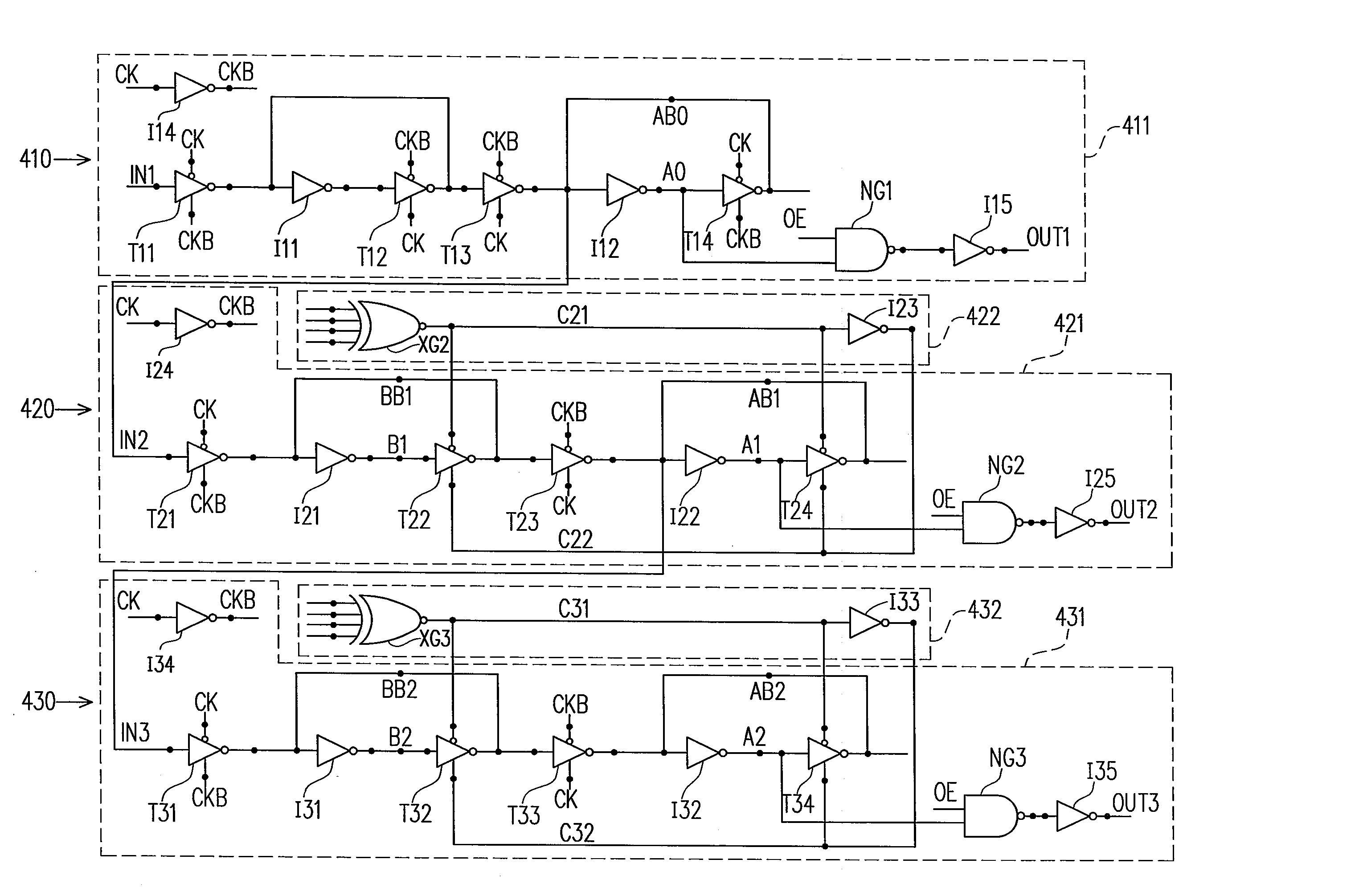
[0024]FIG. 4 is a schematic circuit diagram of a shift register according to a preferred embodiment of the present invention. The shift register of FIG. 4 includes three stage circuits 410, 420, and 430, wherein the first stage circuit 410 only includes a shift circuit 411; each of the other two stage circuits includes a shift circuit and a logic circuit. In other words, the stage circuit 420 includes a shift circuit 421 and a logic circuit 422, and the stage circuit 430 includes a shift circuit 431 and a logic circuit 432.

[0025]The shift circuits 411, 421, and 431 receive input signals IN1-3 and provide output signals OUT1-3 respectively. Each of the output signals is obtained through the logic calculation and delaying of the input signal. The first input signal IN1 is provided by an external system and each of the other input signals is provided to the next stage circuit by the previous stage circuit. The logic circuit 422 is used to produce at least one control signal according t...


PUM


Abstract

A shift register including a plurality of stage circuits is provided. Each of the stage circuits has a shift circuit for receiving an input signal and providing an output signal. The output signal is obtained through the logic calculation and delaying of the input signal. Each of the stage circuits, except the first one, further includes a logic circuit used to produce at least one control signal according to the internal signals of the containing stage circuit, so as to replace at least one of the required clock signals during the operation of the corresponding shift circuit.

Description

BACKGROUND OF THE INVENTION[0001]1. Field of Invention[0002]The present invention relates to a shift register, and more particularly, to a shift register used for conducting logic calculations on internal signals to replace clock signals.[0003]2. Description of Related Art[0004]At present, the shift register has been widely used, such as in the source driver and gate driver of the thin film transistor liquid crystal display (TFT LCD) panel. The shift register is formed by connecting a plurality of stage circuits in series. FIG. 1 is a schematic circuit diagram of one of the stage circuits of the conventional shift register.[0005]The stage circuit in FIG. 1 includes inverters I1-I4, three-state inverters T1-T4, and an NAND gate NG. The stage circuit of FIG. 1 receives an input signal IN from the previous stage circuit, and provides an output signal OUT when an output enable signal OE is enabled. The inverter I3 receives a clock signal CK and outputs an inverted clock signal CKB. The ...

Claims


Application Information

Patent Timeline
Patent Type & Authority Patents(United States)
IPC IPC(8): G11C21/00
CPCG11C19/00
Inventor TSAI, CHENG-HUNGHUANG, CHUN-YAOLIAO, YI-FENG
Owner CHUNGHWA PICTURE TUBES LTD
Why Eureka
Try Eureka