Method of measuring the speed of a fluid

US20210010840A1Pending Publication Date: 2021-01-14SAGEMCOM ENERGY & TELECOM

Image

  • Method of measuring the speed of a fluid
  • Method of measuring the speed of a fluid

Examples


Embodiment Construction

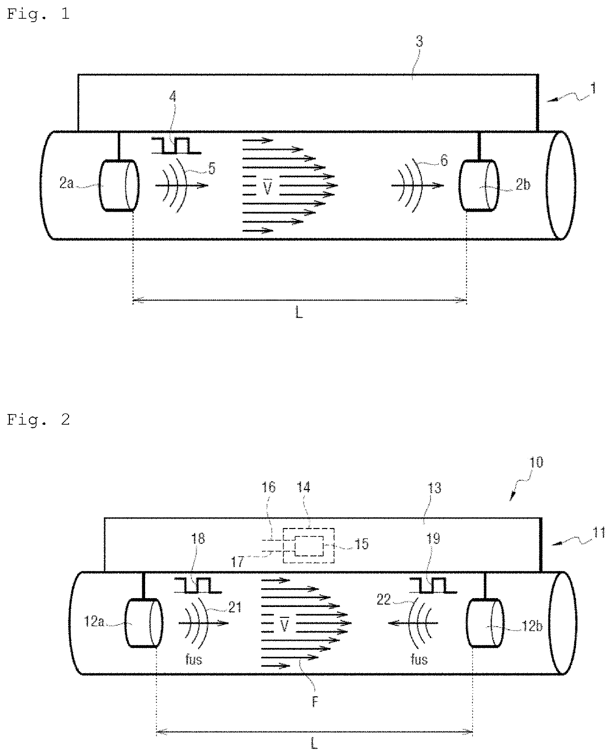
[0055]With reference to FIG. 2, the method of the invention for measuring a fluid speed is performed in this example in an ultrasonic water meter 10.

[0056]The ultrasonic water meter 10 comprises both a duct through which there flows water delivered by a distribution network to an installation, and also a water speed measurement device 11.

[0057]Water flows in the duct from upstream to downstream, as represented by the direction of arrows F, however it could equally well flow from downstream to upstream.

[0058]The measurement device 11 comprises a first transducer 12a, a second transducer 12b, and a measurement module 13 connected to the first transducer 12a and to the second transducer 12b.

[0059]The first transducer 12a and the second transducer 12b are paired. In this example, the first and second transducers 12a and 12b are piezoelectric transducers.

[0060]The measurement module 13 includes a processor component adapted to execute instructions of a program for performing the measure...


PUM


Abstract

A method of measuring the speed of a fluid, comprising the successive steps of: causing the processor component to emit at the same emission time both a first electrical excitation signal that is applied as input to a first transducer and also a second electrical excitation signal that is applied as input to a second transducer, such that the first transducer generates a first ultrasonic signal and such that the second transducer generates a second ultrasonic signal; putting the processor component on standby; reactivating the processor component after a predetermined standby duration; causing the first ultrasonic signal to be acquired by the second transducer and then by the processor component, and causing the second ultrasonic signal to be acquired by the first transducer and then by the processor component; using a value DToF to estimate the speed of the fluid.

Description

[0001]The invention relates to the field of ultrasonic fluid meters.BACKGROUND OF THE INVENTION[0002]In order to measure the flow rate of a fluid flowing in a pipe, an ultrasonic fluid flow meter conventionally makes use of a device for measuring the speed of the fluid by emitting and receiving ultrasonic signals.[0003]The measurement device includes a duct connected to the pipe in which the fluid flows. In order to measure the fluid speed, ultrasonic signals are emitted into the duct to travel along a path of defined length, the travel times taken by the ultrasonic signals to travel along the path of defined length both from upstream to downstream and from downstream to upstream are measured, and the speed of the fluid is estimated on the basis in particular of the defined length and of the difference between the travel times.[0004]Such a measurement device 1, sometimes referred to as a “classical pipe” device, is shown in FIG. 1. The measurement device 1 comprises a first transduc...

Claims


Application Information

Patent Timeline
14 Jan 2021
Publication
US20210010840A1
IPC
G01F1/66; G01P5/24; G01N29/024
CPC
G01F1/668; G01N29/024; G01P5/248; G01P5/245; G01F1/667
Inventors
TEBOULLE, HENRI