Image forming apparatus

a technology of image forming apparatus and forming plate, which is applied in the direction of printing, other printing apparatus, etc., can solve the problems of increasing the cost of the printer and the difficulty of applying to the stationary printer, and achieve the effect of preventing the increase of the space necessary for the installation of the image forming plate and simple and inexpensive structur

Inactive Publication Date: 2009-03-31
FUNAI ELECTRIC CO LTD
View PDF14 Cites 11 Cited by
  • Summary
  • Abstract
  • Description
  • Claims
  • Application Information

AI Technical Summary

Benefits of technology

[0006]The present invention is conceived to solve the above mentioned problems of the conventional printers and purposed to provide an image forming apparatus, and especially, an inkjet printer of low cost and compact which cab feed thick recording paper sheets such as postcards smoothly without being deformed.
[0010]By such a configuration, when an image is formed on a second recording paper sheet such as a postcard which is relatively thick, the second recording paper sheets are loaded on the second tray portion having the second elevation angle with respect to the gentler than that of the first tray portion, so that the second recording paper sheet can be inserted into the paper conveying path with the gentler elevation angle. Thus, the deformation of the second recording paper sheet in the conveyance along the paper conveying path due to, for example, paler feed roller can be prevented by simple and inexpensive structure that the second tray portion is only attached to the rectangular aperture formed on the first tray portion. Furthermore, the second tray portion can be formed to be stored in the rectangular opening when it is unused, so that increase of a space necessary to install the image forming apparatus can be prevented.

Problems solved by technology

However, the constitution of the paper feed tray becomes complex and a number of components constituting the tray increases, thereby causing the increase of cost of the printer.
Although such a constitution is effective to be applied to a portable printer posture of which can easily be changed by a user, it is difficult to be applied to a stationary printer.

Method used


Image

  • Image forming apparatus
  • Image forming apparatus
  • Image forming apparatus

Examples


Embodiment Construction

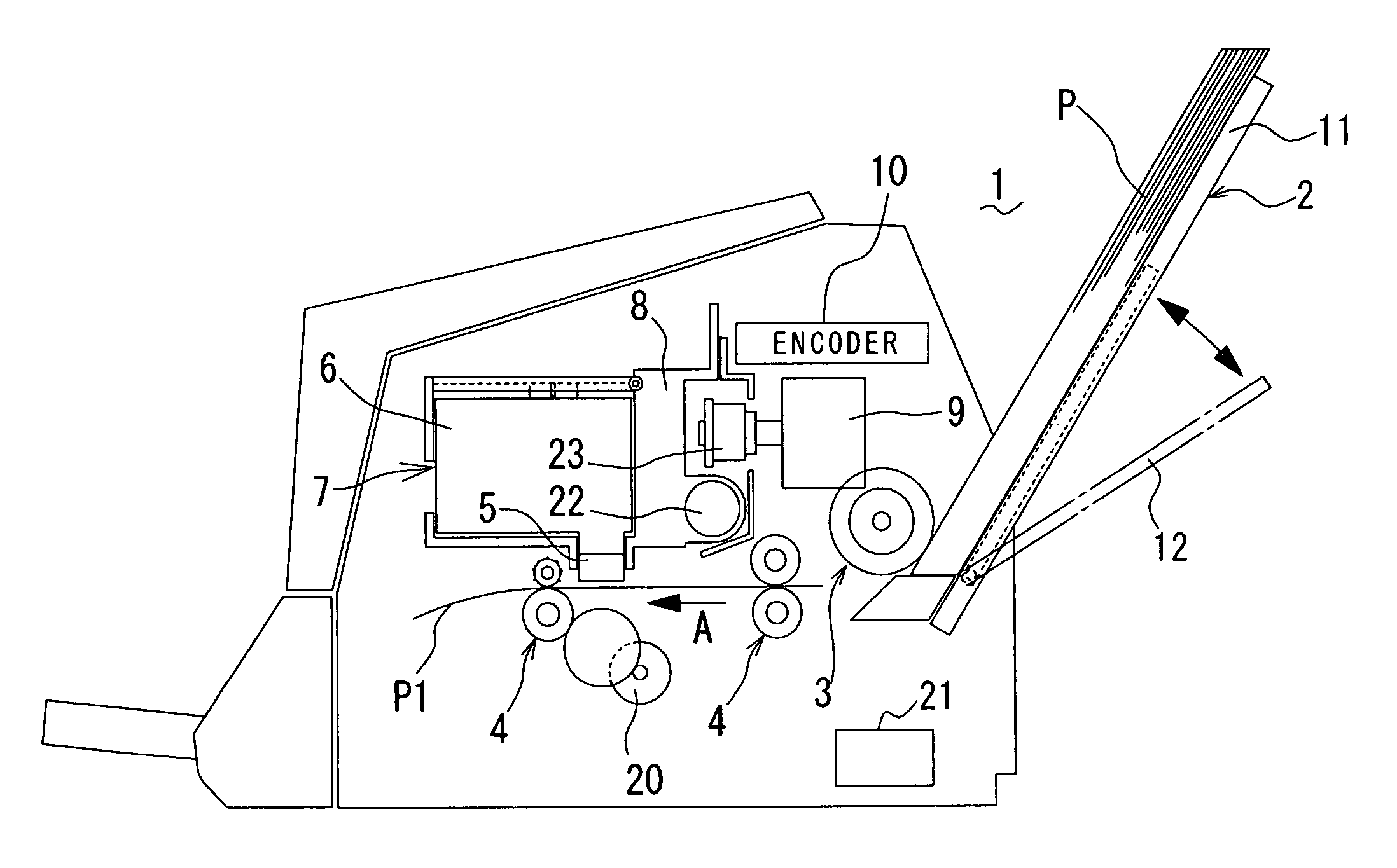
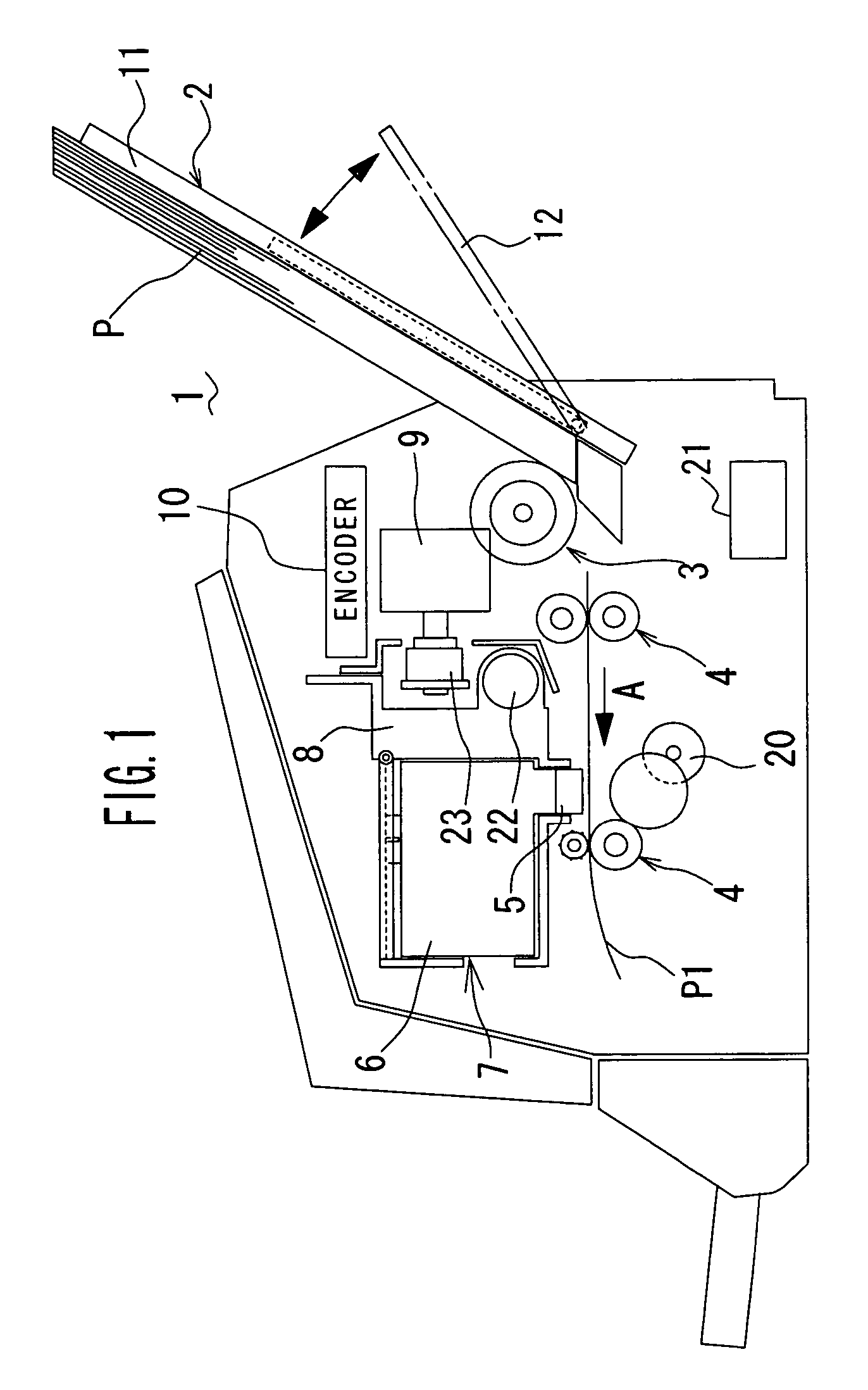
[0015]An inkjet printer which is an example of an image forming apparatus in accordance with an embodiment of the present invention is described with reference to figures. FIG. 1 shows a configuration of the inkjet printer.

[0016]The inkjet printer 1 comprises a paper feed tray 2 on which one or a plurality of recording paper sheets is loaded, a paper feed roller 3 provided to face a lower end portion of the paper feed tray 2 and picking up and conveying a recording paper sheet P into an inside of a main body of the printer 1, conveying rollers 4 for conveying a recording paper sheet P1 which is fed into the inside of the main body of the printer 1 along a paper conveying path A. A carriage 8 is provided above the paper conveying path A so that the carriage is slidably held on a shaft 22 in a direction perpendicular to a paper conveying direction and reciprocally moved along the shaft 22 by a driving force of a carriage driving motor 9 via a belt 23 and so on.An ink cartridge 7 is de...


PUM


Abstract

In an image forming apparatus such as an inkjet printer, deformation of a thick recording paper sheet such as a postcard in the conveyance thereof is prevented by a simple and inexpensive structure. A rectangular aperture corresponding to a size of the postcard is formed on a first tray portion, and a second tray portion is attached to the rectangular aperture. The second tray portion is rotatably borne at a front end thereof on the first tray portion, and linked with the first tray portion at a rear end by link members so that the rotation angle of the second tray portion with respect to the first tray portion is restricted. When the second tray portion is opened, the second tray portion is held with an elevation angle with respect to a paper conveying path gentler than that of the first-tray portion, so that the postcard can be inserted into the paper conveying path with a gentle elevation angle. Consequently, the deformation of the postcard can be prevented.

Description

BACKGROUND OF THE INVENTION[0001]1. Field of the Invention[0002]The present invention relates to an image forming apparatus, such as an inkjet printer which is suitable for printing images on thick recording paper sheets such as postcards, and so on.[0003]2. Description of the Related Art[0004]Conventionally, techniques for feeding thick recording paper sheets such as postcards smoothly are proposed in a field of printers. For example, Japanese Laid-Open Patent Publication No. 11-222322 discloses a printer having a paper feed tray that an angle of a slope portion thereof provided to face rear faces of recording paper sheets is varied in conjunction with a motion of slidable guides contacting to both side of the recording paper sheets. However, the constitution of the paper feed tray becomes complex and a number of components constituting the tray increases, thereby causing the increase of cost of the printer.[0005]On the other hand, Japanese Laid-Open Patent Publication No. 7-237337...

Claims


Application Information

Patent Timeline
Patent Type & Authority Patents(United States)
IPC IPC(8): B41J2/01B41J29/13
CPCB41J13/0063B41J13/103
Inventor MATSUI, TOSHIHARU
Owner FUNAI ELECTRIC CO LTD
Why Eureka
Try Eureka