Electrical connector

a technology of electrical connectors and spring contacts, applied in the direction of coupling contact members, fixed connections, coupling device connections, etc., can solve the problems of spring contacts losing contact with conductive pads, reducing the reliability of electrical connections between conductive pads and spring contacts,

Inactive Publication Date: 2009-03-31
HON HAI PRECISION IND CO LTD
View PDF8 Cites 12 Cited by
  • Summary
  • Abstract
  • Description
  • Claims
  • Application Information

AI Technical Summary

Benefits of technology

[0008]Accordingly, an object of the present invention is to provide an electrical connector that maintains adequate contact between spring contacts and conductive pads. Additionally, another object of the present invention is to provide an electrical connector that ensures the spring contacts remaining adequately aligned to conductive pads.
[0010]As mentioned above, while the plug assembly is mated into the receiving cavity of the housing, the composition of the tangential force exerted by the spring contacts, is reduced or cancelled or substantially cancelled by the resilient force exerted by the push fingers. Thus, the electrical connector maintains adequate contact between the spring contacts and the corresponding pads of the plug assembly and ensures the spring contacts remaining adequately aligned to conductive pads of the plug assembly .

Problems solved by technology

When the plug assembly shifts, the spring contacts may lose contact with the conductive pads.
Even if the spring contacts do not lose the complete contact with the conductive pads, the spring contacts may only partially contact the conductive pads which diminishes the reliability of the electrical connection between the conductive pads and the spring contacts.

Method used


Image

  • Electrical connector
  • Electrical connector
  • Electrical connector

Examples


Embodiment Construction

[0016]Hereinafter, the present invention will be described in detail with reference to the accompanying drawings.

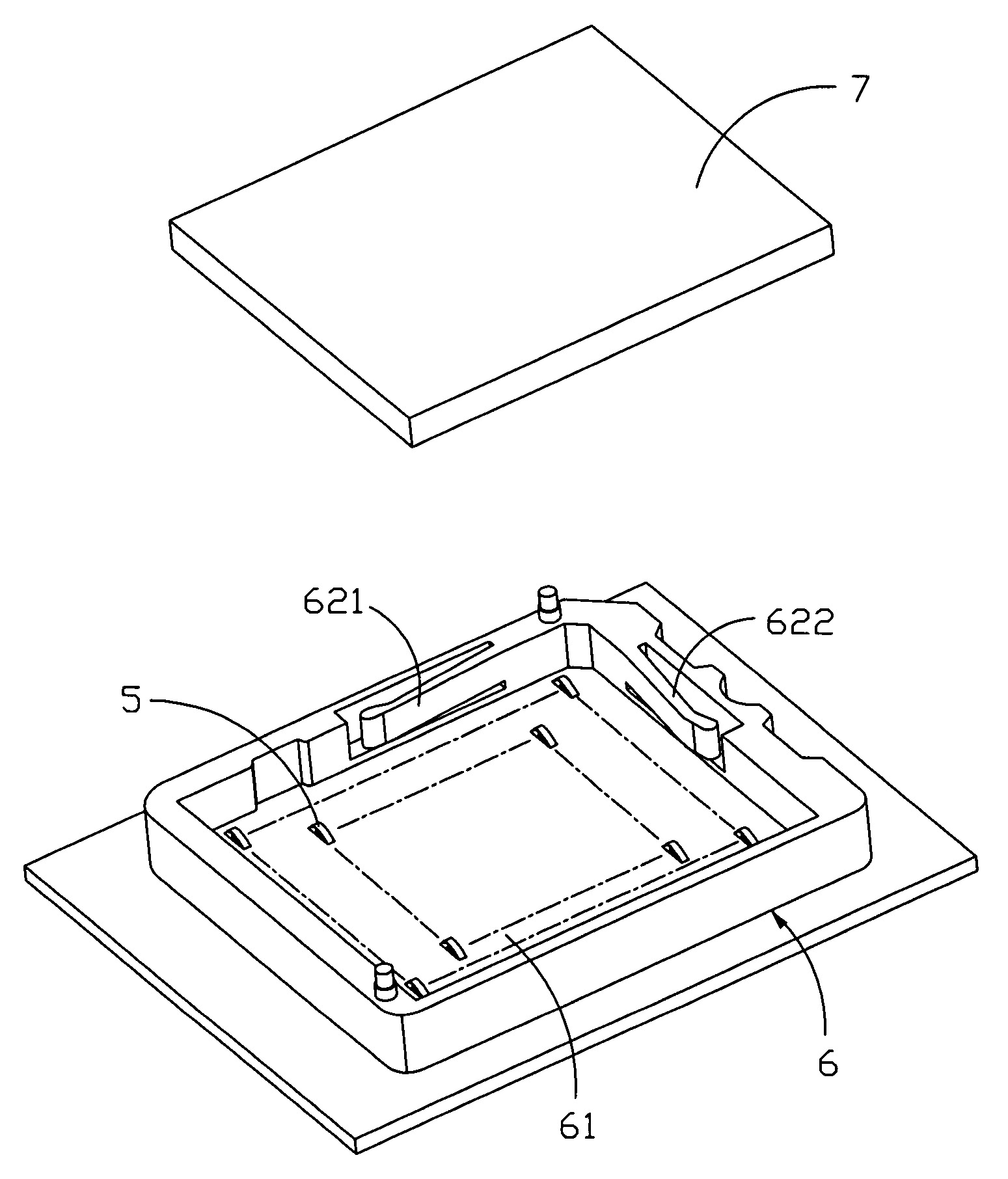
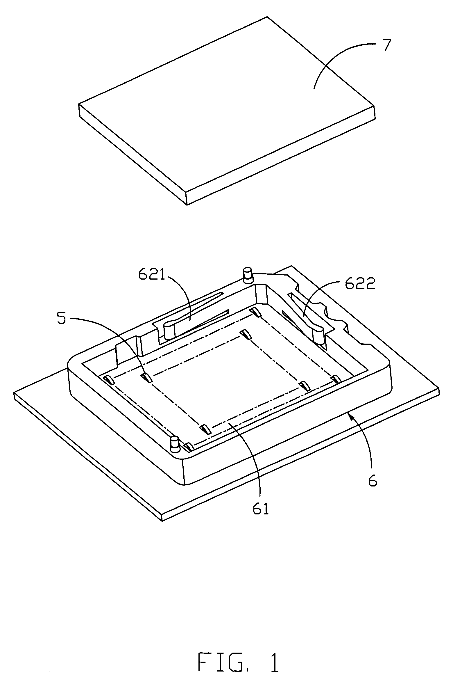
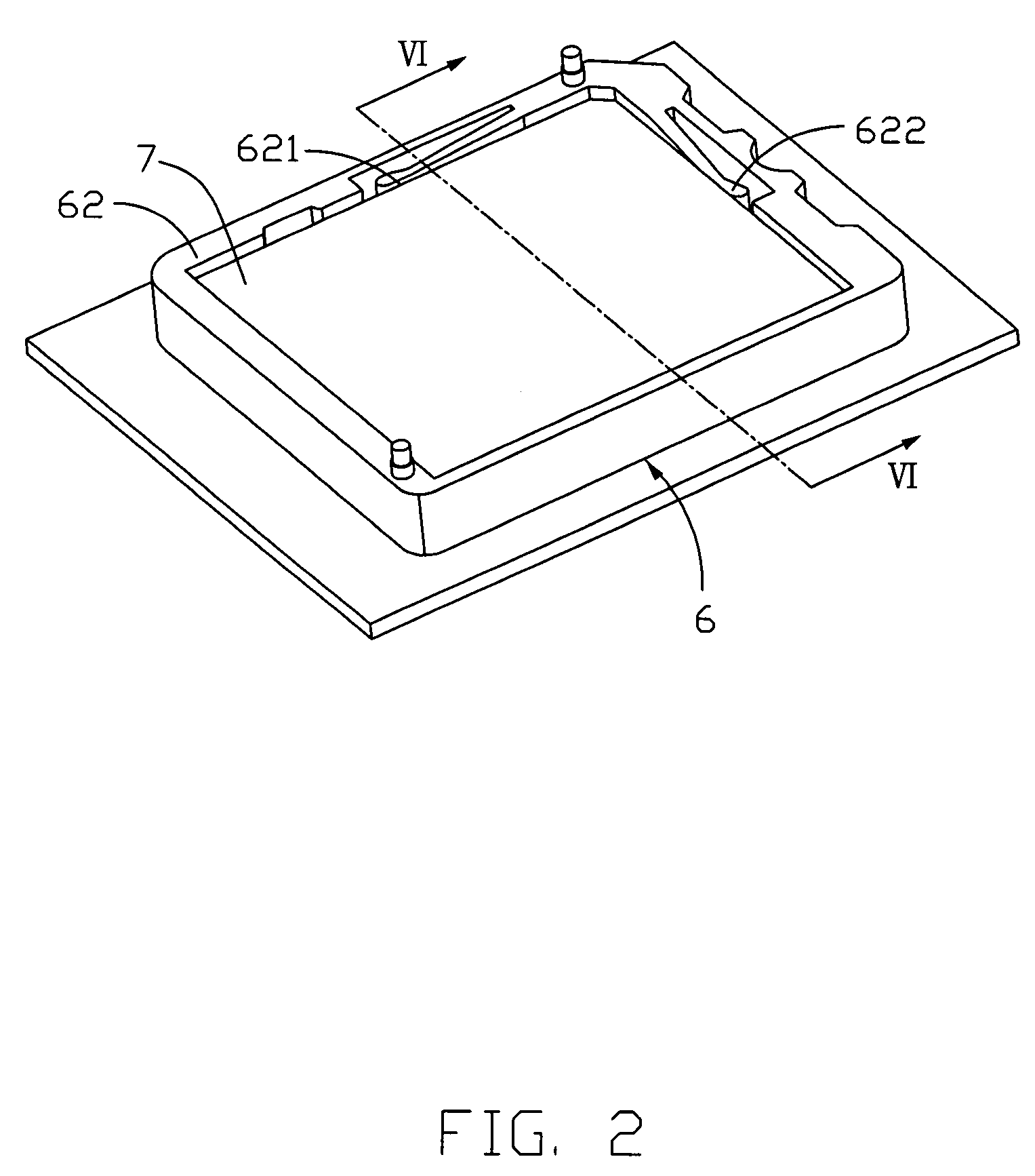
[0017]Referring to FIGS. 1-4, the electrical connector in accordance with a first embodiment of the present invention. The electrical connector includes a dielectric housing 6, which comprises a base 61 having four sidewalls 62 extending therefrom. The base 61 defines a plurality of passageways for receiving the spring contacts 5. The base 61 defines a receiving cavity for receiving the plug assembly 7 together with the four sidewalls. The interior side of the sidewall 62 has a first push finger 621 and a second push finger 622.

[0018]The spring contact 5 is generally of a “C” shape, including a retaining portions 50, which mates with passageways, so as to fix the spring contact 5 in the passageways. A first and second resilient arm 51, 52 extends symmetrically from the two opposite sides of the retaining portion 50. End of the first resilient arm 51 of the contact 5 forms...


PUM


Abstract

Provided is an electrical connector for electrically connecting a plug assembly having a plurality conductive pads to a PCB, comprising a dielectric housing including a base having a plurality of sidewalls extending therefrom; the base defining a receiving cavity for receiving the plug assembly together with said sidewalls; a plurality of spring contacts received in the base, and defining a resilient arm extending above the base, the resilient arm having a contact portion for wiping the corresponding conductive pads of the plug assembly and exerting a tangential component force, while the plug assembly is mated into the receiving cavity of the housing; wherein the base is divided into several sections, each section having a plurality of spring contacts received therein, the spring contacts received in a same section oriented in a same direction but different from those in other sections, sidewalls which is opposite to the composition of the tangential component force defining a plurality of push finger in order to exert resilient force to cancel or substantially cancel or reduce the composition of the tangential component force.

Description

BACKGROUND OF THE INVENTION[0001]1. Field of the Invention[0002]The present invention relates generally to an electrical connector, and more particularly relates to an electrical connector having a plurality of contacts arranged in several different directions.[0003]2. Background of the Invention[0004]Various electronic systems, such as computer, comprise a wide array of components mounted on printed circuit boards, such as daughterboards and motherboards, which are interconnected to transfer signals and power throughout the system. The transfer of signals and power between the circuit boards requires electrical interconnection between the circuit boards. Certain interconnections include a socket assembly, e.g. a LGA socket and a plug assembly, e.g. a CPU module. Some socket assemblies include spring contacts, which are configured to mate with conductive pads on the plug assembly. As the socket assembly and plug mate, the spring contacts exert a normal force on the contact pads, thu...

Claims


Application Information

Patent Timeline
Patent Type & Authority Patents(United States)
IPC IPC(8): H01R12/00H01R12/57H01R12/71
CPCH01R13/2435H01R13/6315
Inventor MA, HAO-YUNHSU, HSIU-YUANHSIAO, SHIH-WEI
Owner HON HAI PRECISION IND CO LTD
Why Eureka
Try Eureka