
Tamper resistant assembly for an electrical receptacle

Active Publication Date: 2009-03-31
HUBBELL INC
View PDF13 Cites 71 Cited by
  • Summary
  • Abstract
  • Description
  • Claims
  • Application Information

AI Technical Summary

Benefits of technology

[0011]The foregoing objectives are basically attained by a tamper resistant assembly including a base member and a first shutter member. A groove has a locking portion connected to a first portion in the base member. A first shutter member having first and second resilient arms is slidably connected to the base member. First and second protrusions extend rearwardly from the first and second resilient arms, respectively, and are movably received in the groove in the base member. The first and second protrusions are disposed in the locking portion of the groove when the shutter member is in a closed position and in the first portion when the shutter member is in an open position. The locking portion prevents separation of the first and second protrusions in the close position to prevent the first and second resilient arms from being separated and to prevent insertion of an object therebetween.
[0012]The foregoing objectives are also basically attained by an electrical receptacle adapted to receive both 15 and 20 amp plugs and having a tamper resistant assembly disposed therein. A front cover has first and second guide ribs connected thereto, and a back housing secured to the front cover. A tamper resistant assembly is disposed between the front cover and the back housing, and includes a base member and a first shutter member. The base member has first and second guide grooves received by the first and second guide ribs to align the tamper resistant assembly with the front cover. A first groove has a locking portion connected to a first portion in the base member. The shutter member is slidably connected to the base member and has first and second resilient arms. First and second protrusions extend rearwardly from the first and second resilient arms, respectively, and are movably received in the first groove in the base member. The first and second protrusions are disposed in the locking portion of the first groove when the shutter member is in a closed position and in the first portion when the shutter member is in an open position. The locking portion prevents separation of the first and second protrusions in the close position to prevent the first and second resilient arms from being separated and to prevent insertion of an object therebetween.

Problems solved by technology

A child inserting, for example, a paper clip or the conductive portion of a toy into the energized conductive elements can be seriously injured.
The slideable shutter members of the Bowden '607 patent do not provide tamper resistance for an electrical receptacle adapted to receive both 15 and 20 amp plugs.

Method used


Image

  • Tamper resistant assembly for an electrical receptacle
  • Tamper resistant assembly for an electrical receptacle
  • Tamper resistant assembly for an electrical receptacle

Examples


Embodiment Construction

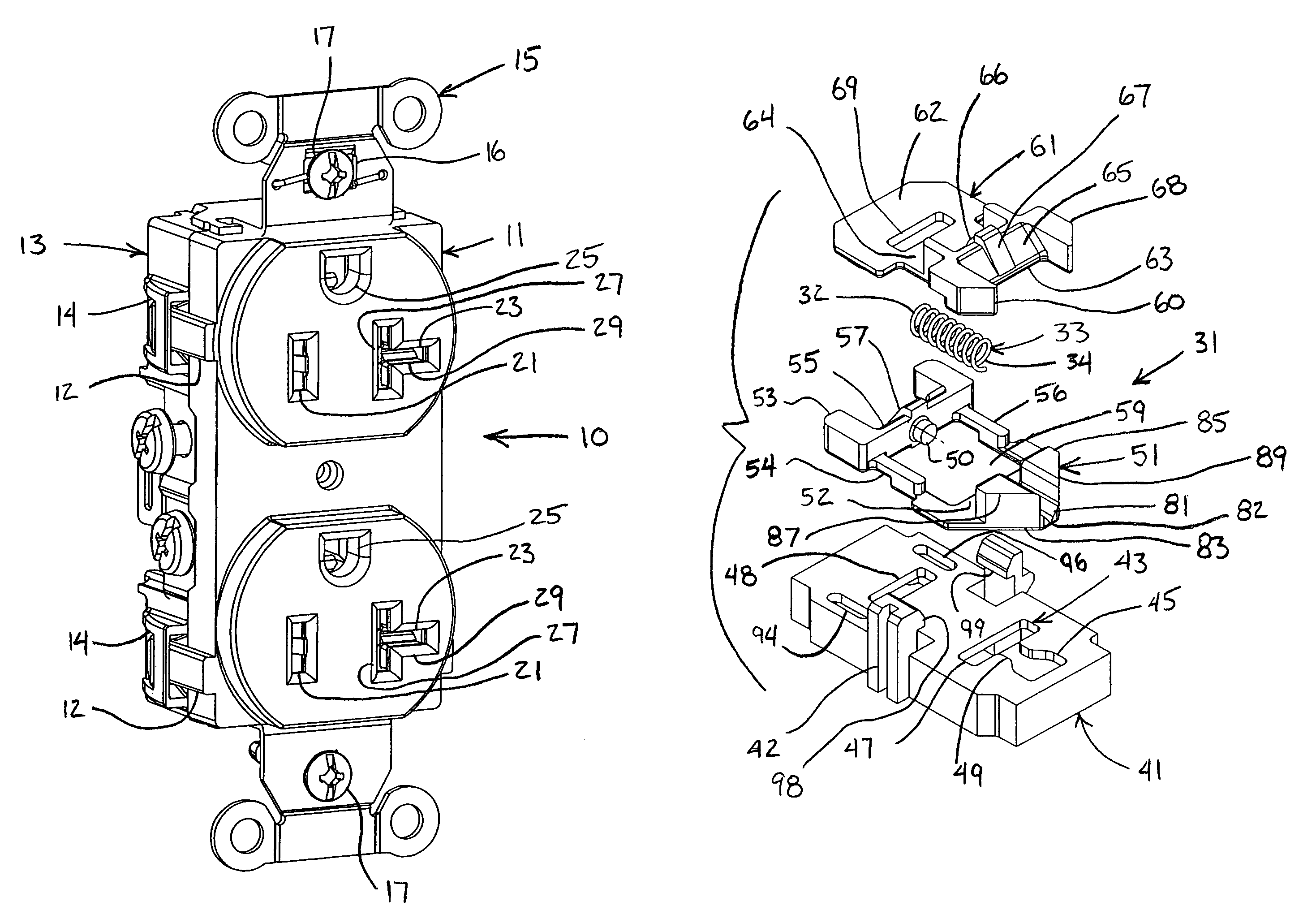
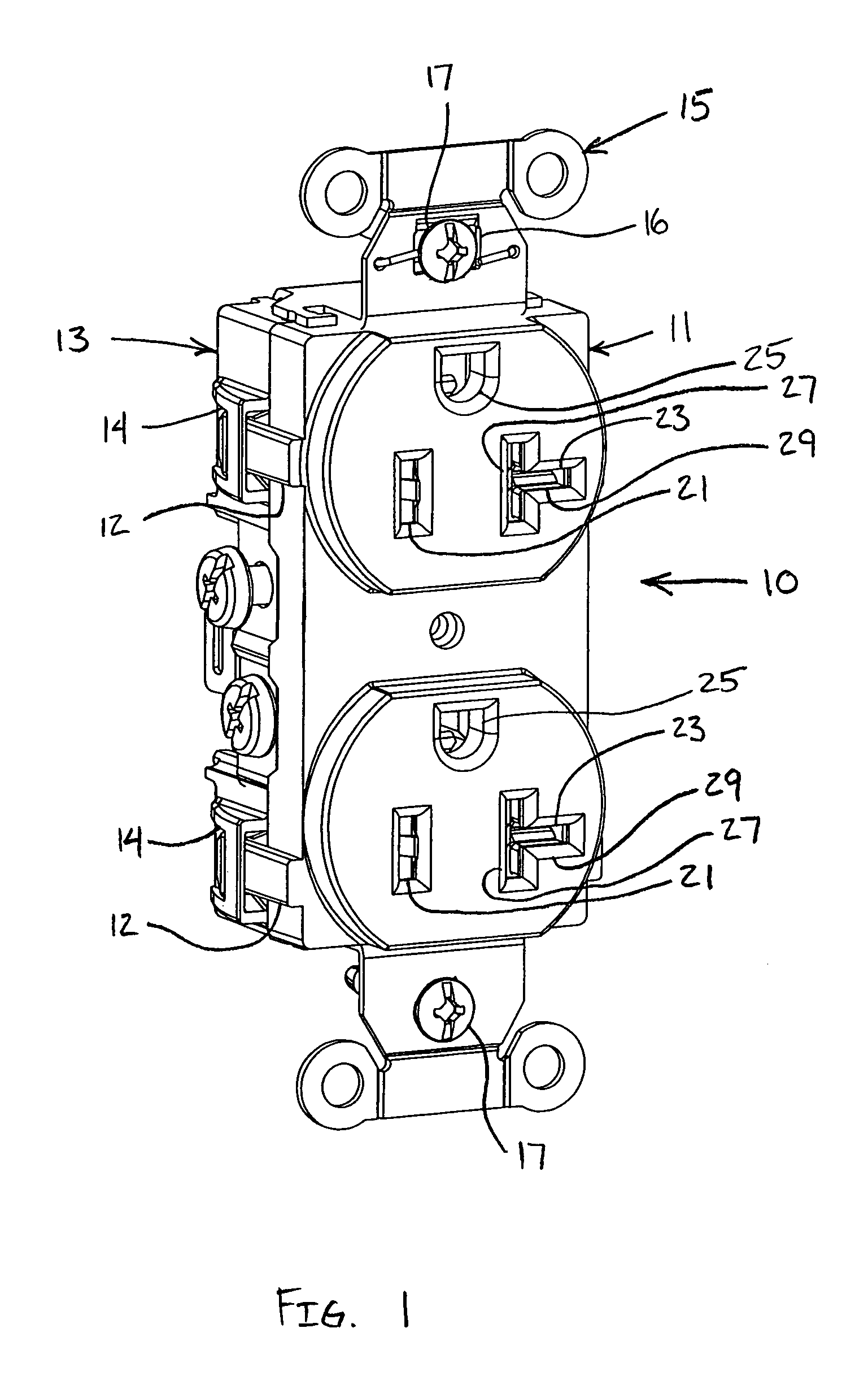
[0028]As shown in FIGS. 1-11, the present invention includes a tamper resistant electrical receptacle 10. A tamper resistant assembly 31 provides tamper resistance for an electrical receptacle 10 adapted to receive both 15 and 20 amp plugs.

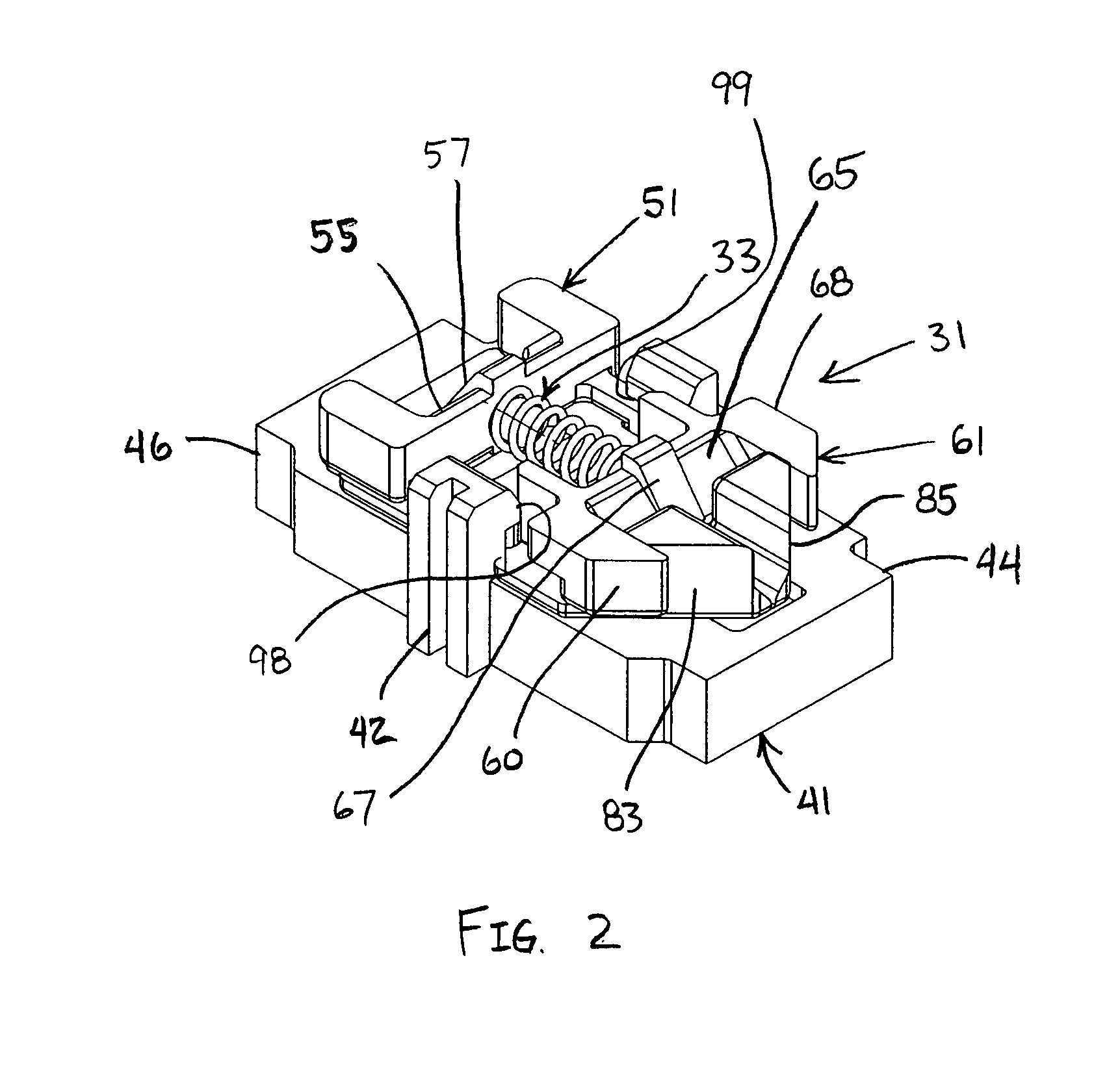
[0029]The tamper resistant assembly 31, as shown in FIGS. 2 and 3, includes a base member 41, a first shutter member 51, a second shutter member 61 and a spring 33. A groove 43 is formed in the base member 41 and has a first portion 45 and a second portion 47 separated by a locking portion 49. First shutter member 51 is slidably connected to the base member 41. A protrusion 91 extends rearwardly from the first shutter member 51 and is movably received in the groove 43 in the base member 41, as shown in FIG. 5. The protrusion 91 is disposed in the first portion 45 of the groove 43 when in an open position, as shown in FIG. 11, and in the locking portion 49 when in the closed position. The locking portion 49 prevents outward movement of the protrusi...


PUM


Abstract

A tamper resistant assembly provides tamper resistance to an electrical receptacle. A groove has a locking portion connected to a first portion in a base member of the tamper resistant assembly. A first shutter member having first and second resilient arms is slidably connected to the base member. First and second protrusions extend rearwardly from the first and second resilient arms, respectively, and are slidably received in the groove in the base member. The first and second protrusions are disposed in the locking portion of the groove when the shutter member is in a closed position and in the first portion when the shutter member is in an open position. The locking portion prevents separation of the first and second protrusions in the closed position to prevent the first and second resilient arms from being separated and to prevent insertion of an object therebetween.

Description

FIELD OF THE INVENTION[0001]The present invention relates to a tamper resistant assembly for an electrical receptacle. More particularly, the present invention relates to a tamper resistant electrical receptacle adapted to receive both 15 and 20 amp plugs. Still more particularly, the present invention relates to a tamper resistant assembly for an electrical receptacle in which the base member of the tamper resistant assembly has a groove for receiving a protrusion of a shutter member to prevent accidental movement of the shutter member.BACKGROUND OF THE INVENTION[0002]A group of electrical receptacles is referred to as “protective” receptacles because some measure has been taken in the construction to protect children and others from harm if they should intentionally or inadvertently insert or attempt to insert an electrically conductive article into the electrically energized portions of the receptacle. Conventional electrical receptacles have a nonconductive face portion with ope...

Claims


Application Information

Patent Timeline
IPC IPC(8): H01R13/44
CPCH01R13/4534H01R13/652H01R24/78H01R27/02H01R25/006H01R2103/00
Inventor VALENTIN, WILLIAM RAMON
Owner HUBBELL INC
Features
  • Generate Ideas
  • Intellectual Property
  • Life Sciences
  • Materials
  • Tech Scout
  • Unparalleled Data Quality
  • Higher Quality Content
  • 60% Fewer Hallucinations
Learn More