Head part for a multi-chamber tube bag

a multi-chamber, tube bag technology, applied in the direction of liquid dispensing, containers, diagnostics, etc., can solve the problems of large discrepancies in the mixing ratio, general prior art disadvantages, and malfunctions of the press-out device, and achieve the effect of simple and economical production and constant mixing ratio

Inactive Publication Date: 2009-03-31
HILTI AG
View PDF6 Cites 12 Cited by
  • Summary
  • Abstract
  • Description
  • Claims
  • Application Information

AI Technical Summary

Benefits of technology

[0007]It is the primary object of the invention to provide a head part for a multi-chamber tube bag which ensures an extensively constant mixing ratio, of two or more components of a chemical mass, on the one hand and can be produced simply and economically on the other hand.
[0009]As a result of the raised portion formed as a projection, for example, the outlet cross section is narrowed at least in some regions and the amount exiting the at least one secondary chamber is restricted or throttled during the process of dispensing the respective components. In this way, a pressure difference is built up between the one component in the main chamber and the at least one other component in the at least one secondary chamber. This pressure difference ensures that the flexible dividing wall between the main chamber and the at least one secondary chamber is loaded only by tensile forces so that they are not displaced or deformed in an unwanted manner and the reference cross-sectional surfaces or output cross-sectional surfaces of the main chamber and of the at least one secondary chamber are maintained throughout the entire dispensing process. In addition, the pressure difference can be ensured and therefore the output cross-sectional surfaces can be maintained through a suitable selection of differences in the viscosity or penetrometer values of the individual components relative to one another. As soon as the multi-chamber tube bag contacts the contact surface and it is opened and pressure is generated on the multi-chamber tube bag, e.g., by means of a press-out piston, a constant mixing ratio of the individual components relative to one another is ensured during the entire press-out process due to the design of the head part according to the invention. This ensures a constant mixing ratio of the individual components even when repeatedly dispensing small amounts of the multi-component mass.
[0012]The press-out opening is preferably arranged in an aligned manner at the contact surface with respect to the position of the outlet of the main chamber in order to enable an extensively linear flow of the component from the main chamber when the multi-chamber tube bag contacts the contact surface at the head part. When the main chamber, for example, in a multi-chamber tube bag with a substantially circular cross section, is arranged substantially centrically in the multi-chamber tube bag, the press-out opening is advantageously provided in the center of the contact surface in order to make it possible for the component to flow from the main chamber linearly to a great extent. In case of a substantially lateral arrangement of the main chamber, the press-out opening is provided at the contact surface corresponding to the position of the outlet of the main chamber. The arrangement of the outlet opening in alignment with the position of the outlet of the main chamber ensures that the predetermined amount of the one component from the main chamber is dispensed substantially directly in combination with the restricted mass flow of the at least one other component from the at least one secondary chamber.
[0013]The head part is advantageously fixed to the multi-chamber tube bag. For example, the head part is glued or welded to the multi-chamber tube bag, e.g., in situ. The head part is preferably preassembled with the multi-chamber tube bag. This makes it possible to connect the head part to the multi-chamber tube bag under controlled conditions, which improves the correct alignment of the head part to the multi-chamber tube bag or the correct alignment of the multi-chamber tube bag to the head part and the quality of the connection is improved compared to making the connection in situ. The usability of the multi-chamber tube bag is likewise improved when preassembled compared with making the connection in situ.
[0017]In another variation, an inner tube which takes over the function of the head part according to the invention can be provided at an exchangeable mixing element which is arranged, for example, at a cartridge. The mixing element has, for example, a connection with an internal thread and the inner tube is arranged coaxial to the dispensing opening of the cartridge, so that the free end of the inner tube, as raised portion, narrows the outlet area of at least the at least one secondary chamber of the multi-chamber tube bag in the contacting state of the multi-chamber tube bag. The mixing element can also have an external thread for the connection of the mixing element to an internal thread at the dispensing opening of the cartridge, wherein the free end, as raised portion, narrows the outlet area of at least the at least one secondary chamber of the multi-chamber tube bag in the contacting state of the multi-chamber tube bag.

Problems solved by technology

This general prior art is disadvantageous because a constant mixing ratio is not adequately ensured.
The dividing walls of the multi-chamber tube bag can be displaced or creased in an unwanted manner between the individual chambers during the press-out process so that considerable discrepancies in the mixing ratios can result.
In addition, an uneven folding of the foils can lead to malfunctions in the press-out device.
When small amounts of multi-component mass must be dispensed repeatedly, the strict safety requirements, e.g., for mortars for chemical fastenings, may not be met in the packaging known from the general prior art.
The known solution is disadvantageous in that the head part is complicated to produce.

Method used


Image

  • Head part for a multi-chamber tube bag
  • Head part for a multi-chamber tube bag
  • Head part for a multi-chamber tube bag

Examples


Embodiment Construction

Detailed Description of the Preferred Embodiments

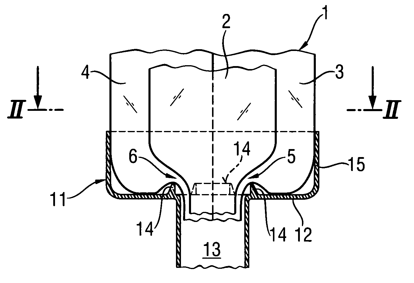
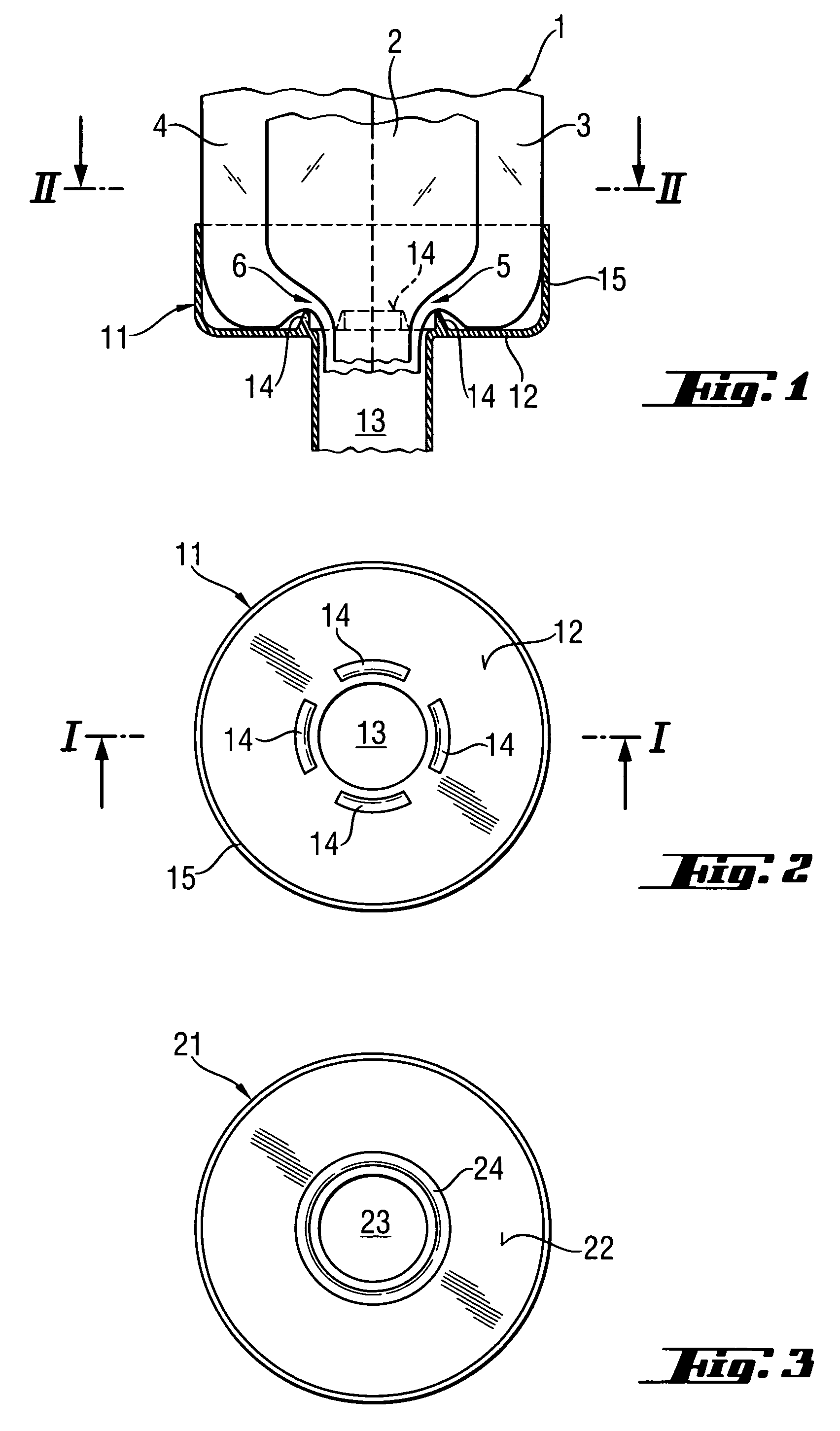
[0028]FIGS. 1 and 2 show a head part 11 according to the invention which is glued to a multi-chamber tube bag 1 on the work side. The multi-chamber tube bag 1 for a three-component mass has a main chamber 2 and two secondary chambers 3 and 4 arranged at the outer circumference of the multi-chamber tube bag 1. In this embodiment example, the multi-chamber tube bag 1 has a circular cross-sectional surface in cross section.

[0029]The head part 11 has a disk-shaped contact surface 12 and a press-out opening 13. A connection for a mixer element which can be screwed on, for example, can be provided at the press-out opening 13. Further, the head part 11 has a collar 15 which at least partially encompasses the end area of the multi-chamber tube bag 1. Four raised parts 14 which are constructed as projections and which are oriented in the direction of the multi-chamber tube bag 1 are formed at the contact surface 12. The raised parts 14 narrow ...


PUM


Abstract

A head part (11) for a multi-chamber tube bag (1) with a multi-component mass which can be pressed out, having a main chamber (2) for a first component and two secondary chambers (3, 4) for two other components, has a disk-shaped contact surface (12) for the multi-chamber tube bag (1) surrounding a press-out opening (13). At the contact surface (12), a plurality of raised portions (14) project toward the multi-chamber tube bag (1) and are provided at the head part (11) for narrowing the outlet regions (5, 6) of the two secondary chambers (3, 4) of the multi-chamber tube bag (1) when the multi-chamber tube bag (1) bears against the contact surface (12).

Description

FIELD OF THE INVENTION[0001]The invention is directed to a head part for a multi-chamber tube bag with a multi-component mass which can be pressed out, having a main chamber for a first component and at least one secondary chamber for another component. The head part has a substantially flat contact surface for the multi-chamber tube bag surrounding a press-out opening.DESCRIPTION OF THE PRIOR ART[0002]Multi-component chemical masses are used in different areas of day-to-day life and particularly in construction, e.g., as mortar, glue, sealing compound or insulating foam. The masses mostly comprise a hardener, a component to be hardened, and fillers, and possibly other additives. Since these individual components react with one another, they are stored separately until the ready-to-use mass is produced. The individual components are fed to a mixing element so as to be metered in a given amount ratio, for example, by means of a press-out device, and the individual components are mixe...

Claims


Application Information

Patent Timeline
Patent Type & Authority Patents(United States)
IPC IPC(8): A61B19/00B05C17/005B65D81/32B65D83/00
CPCB05C17/00583B05C17/00586B65D81/3244B65D83/0072
Inventor BAESSLER, ARMINGINTER, HERBERTWILLNER, RALF
Owner HILTI AG
Why Eureka
Try Eureka