
Stud welding apparatus with composite cable

a welding apparatus and composite cable technology, applied in the direction of power cables, cables, manufacturing tools, etc., can solve the problems of inherently difficult handling and manipulation of bundle cables, prone to damage, and weak control cables associated with bundle bundles, and achieve the effect of shortening the service life of control cables

Active Publication Date: 2009-03-31
NELSON STUD WELDING
View PDF24 Cites 13 Cited by
  • Summary
  • Abstract
  • Description
  • Claims
  • Application Information

AI Technical Summary

Benefits of technology

"The patent describes a device for welding studs onto a surface. The device includes a power supply and a tool with a welding head. A special cable is used to connect the tool to the power supply. This cable has two ends, and it has a conductor and a control lead that are surrounded by a layer of non-conductive material. The technical effect of this design is that it allows for safer and more efficient welding of studs onto surfaces."

Problems solved by technology

The bundled cables are inherently difficult to handle and manipulate and are prone to damage when used in a typical work environment where the cables are moved and exposed to hostile welding conditions with chafe, bend, twist, cut, heat, fire, welding spatter, stretch, whip, tear, wear and abrasion.
Additionally, a control cable associated with the bundle is typically much weaker than the larger welding current cable due to its smaller diameter and thinner jacket.
As such, the control cable is subject to a shorter service life when exposed to the same wear and abrasion.
Additionally, the end connectors for a control cable are also weaker than the connector for the welding current cable such that when an operator pulls or otherwise manipulates a cable the control cable is subject to failure due to the weaker connector.
Rapid movement of the weld head exerts inordinate torsion and bending.
The straight control cable does not contain slack to absorb the stretch and compression, causing pre-mature fatigue failure and loss of conductivity.
Prior art cables that include a polyester gas conduit are typically not protected and are subject to collapse, melting or puncture.
Downtime associated with unexpected cable failures can be very costly to a manufacturer.

Method used


Image

  • Stud welding apparatus with composite cable
  • Stud welding apparatus with composite cable
  • Stud welding apparatus with composite cable

Examples


Embodiment Construction

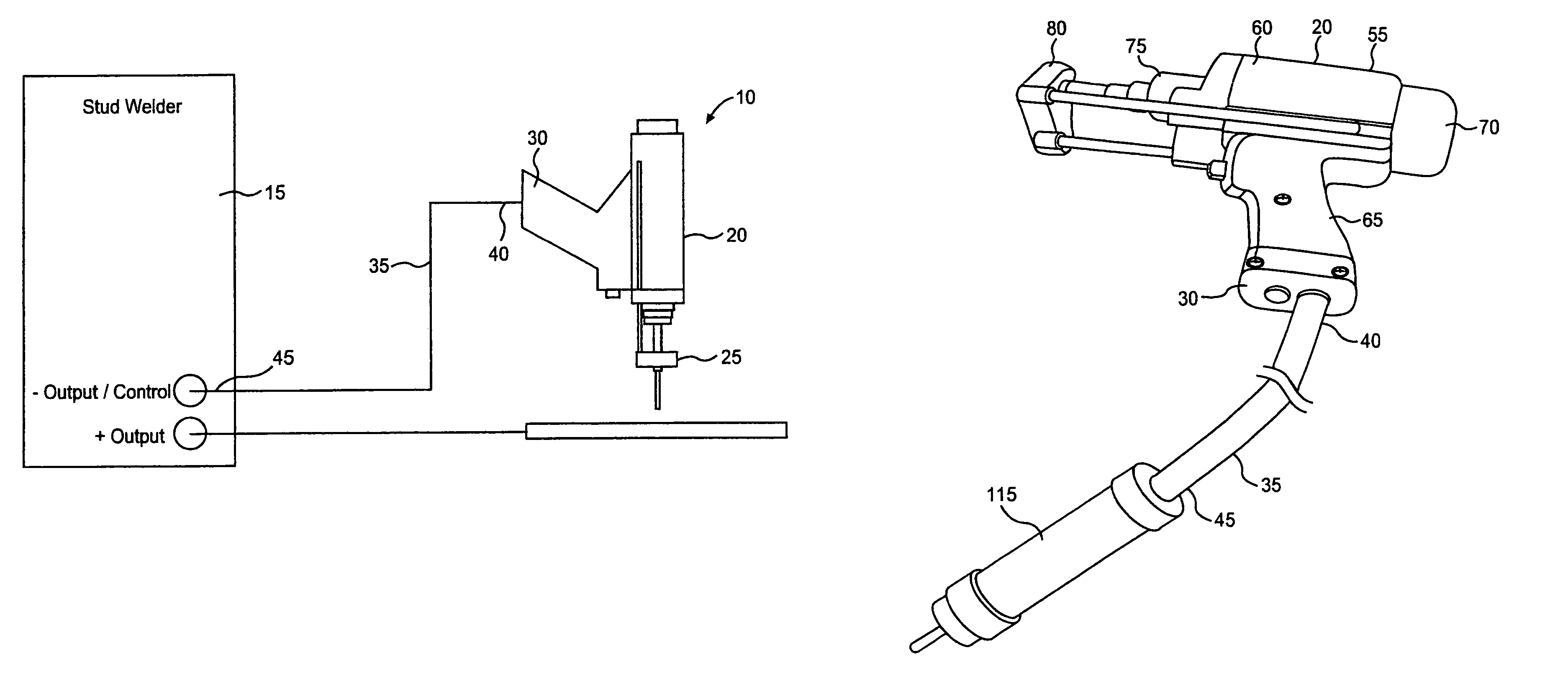
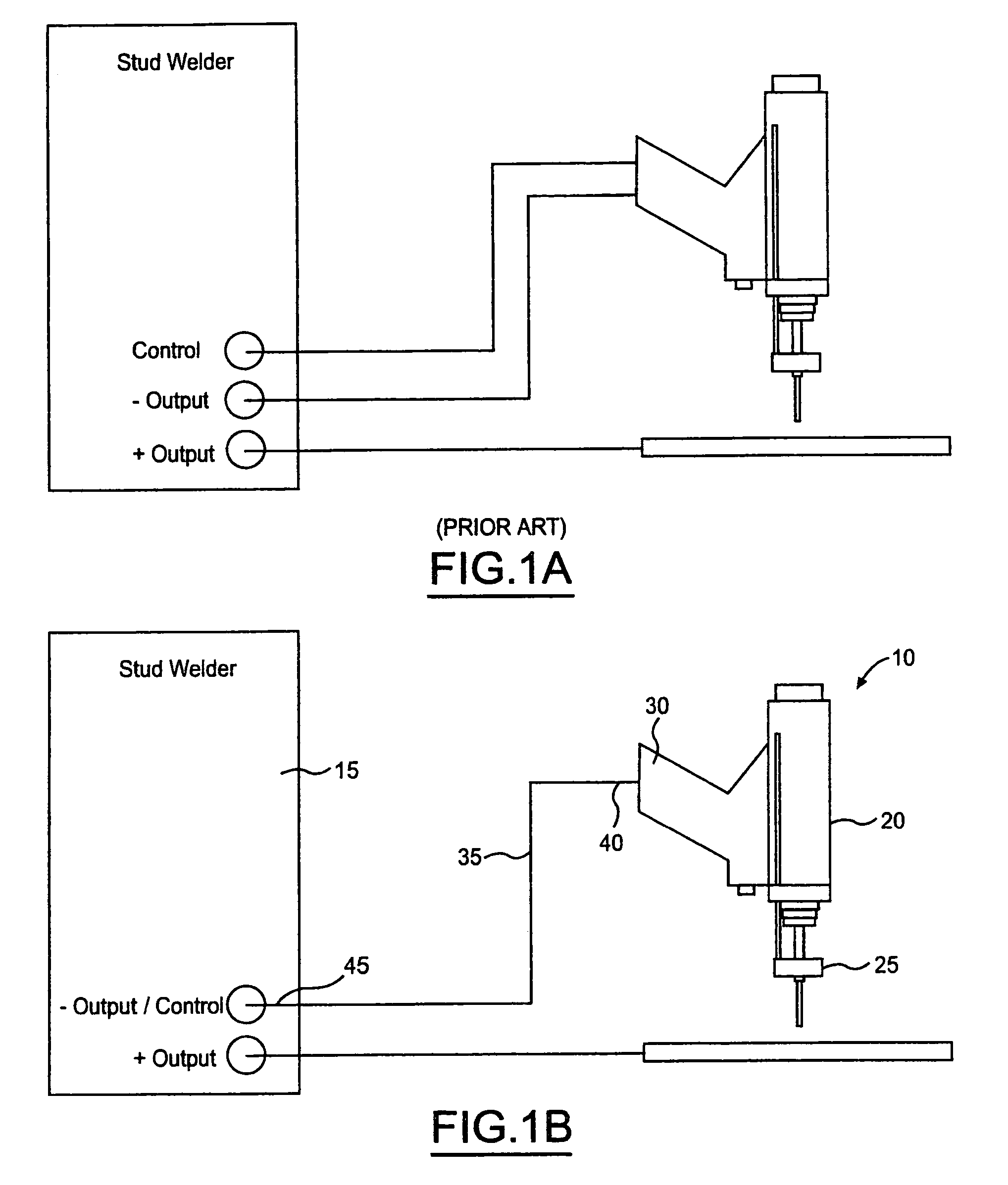
[0019]Referring to FIG. 1B, there is shown a stud welding apparatus 10 according to the present invention. A stud welding apparatus 10, as the term is used through out the specification and claims includes any welding apparatus that includes the steps of: placing a part to create a short circuit, drawing an arc between the part and another piece, engaging a weld current to melt the part and the other piece and then plunging the part into the piece to create a weld. The part is not limited to stud shaped parts but rather includes any part such as a bracket, angle piece, boss or any other part capable of being joined by the above operation.

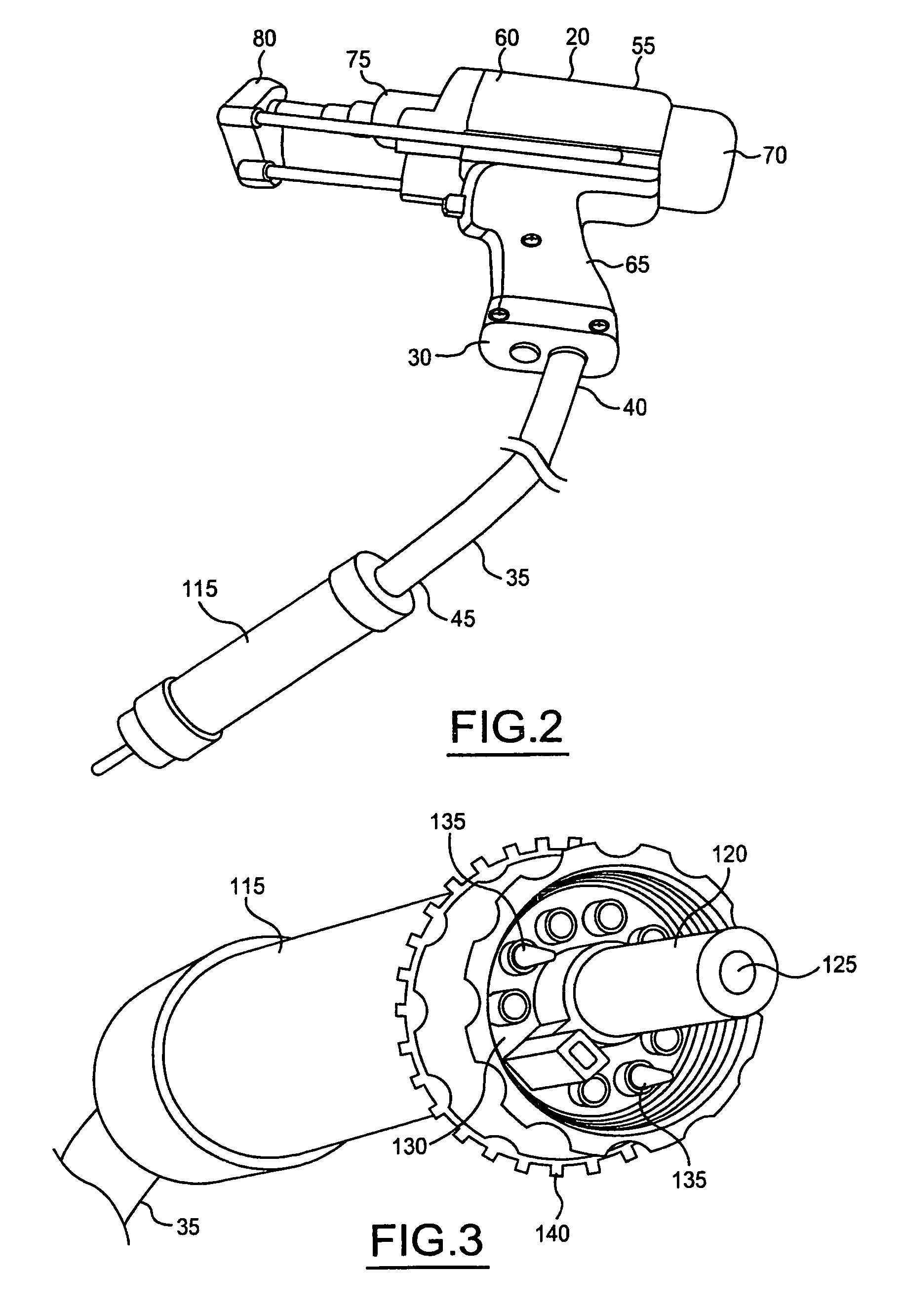
[0020]The stud welding apparatus 10 includes a power supply 15 and a stud welding tool 20. The power supply 15 includes appropriate control circuitry for controlling the stud welding tool 20. The stud welding tool 20 includes a welding head portion 25 and a cable receiving portion 30. A composite cable 35 includes first and second ends 40, 45. The f...


PUM

PropertyMeasurementUnit
durometer hardnessaaaaaaaaaa
non-black coloraaaaaaaaaa
electrically conductiveaaaaaaaaaa

Abstract

A stud welding apparatus includes a power supply and a stud welding tool having a welding head portion and a cable receiving portion. A composite cable having first and second ends is coupled at a first end to the stud welding tool at the cable receiving portion and to the power supply at the second end of the composite cable. If the stud feeder is present, the second end of the composite cable can be coupled to the stud feeder. The composite cable includes a conductor having no individual electrical isolation and at least one control lead electrically isolated from the conductor. The conductor and the at least one control lead are surrounded by an outer non-conductive layer.

Description

FIELD OF THE INVENTION[0001]The invention relates to a stud welding apparatus, and more particularly to a stud welding apparatus having a composite cable.BACKGROUND OF THE INVENTION[0002]Typical stud welding apparatus of the prior art include a stud welding gun having separate cables for supplying a welding current, electrical control signals, and other functions such as a gas conduit for supplying inert welding gas, pressure tubes for pneumatic controls, and tubes for feeding studs. Such prior art welding apparatus include the separate cables that are usually taped or otherwise bundled together with a thin sheath in a “cable package”. The bundled cables are inherently difficult to handle and manipulate and are prone to damage when used in a typical work environment where the cables are moved and exposed to hostile welding conditions with chafe, bend, twist, cut, heat, fire, welding spatter, stretch, whip, tear, wear and abrasion.[0003]Additionally, a control cable associated with t...

Claims


Application Information

Patent Timeline
Patent Type & Authority Patents(United States)
IPC IPC(8): B23K9/20
CPCB23K9/201B23K9/202B23K9/32F16L25/01H01B9/001
Inventor HSU, CHRIS
Owner NELSON STUD WELDING
Learn More