Light source for LCD back-lit displays

a backlit display and light source technology, applied in the field of light sources for lcd backlit displays, can solve the problems of poor adaptability of light sources based on fluorescent lights to such thin displays, less attractive for battery operated devices, and the difficulty of implementing solutions based on fluorescent lights

Active Publication Date: 2009-04-07
TAIWAN SEMICON MFG CO LTD
View PDF17 Cites 113 Cited by
  • Summary
  • Abstract
  • Description
  • Claims
  • Application Information

AI Technical Summary

Problems solved by technology

However, such sources require high driving voltages which makes them less attractive for battery operated devices.
Light sources based on fluorescent lights are poorly adapted for such thin displays.
As the thickness of the light box is reduced, solutions based on fluorescent lights become more difficult to implement and still maintain a high power conversion efficiency.
Unfortunately, LEDs suffer from aging problems.
However, even with this approximation, the additional circuitry and detectors associated with the monitoring operation are a significant factor in the cost of the display.

Method used


Image

  • Light source for LCD back-lit displays
  • Light source for LCD back-lit displays
  • Light source for LCD back-lit displays

Examples


Embodiment Construction

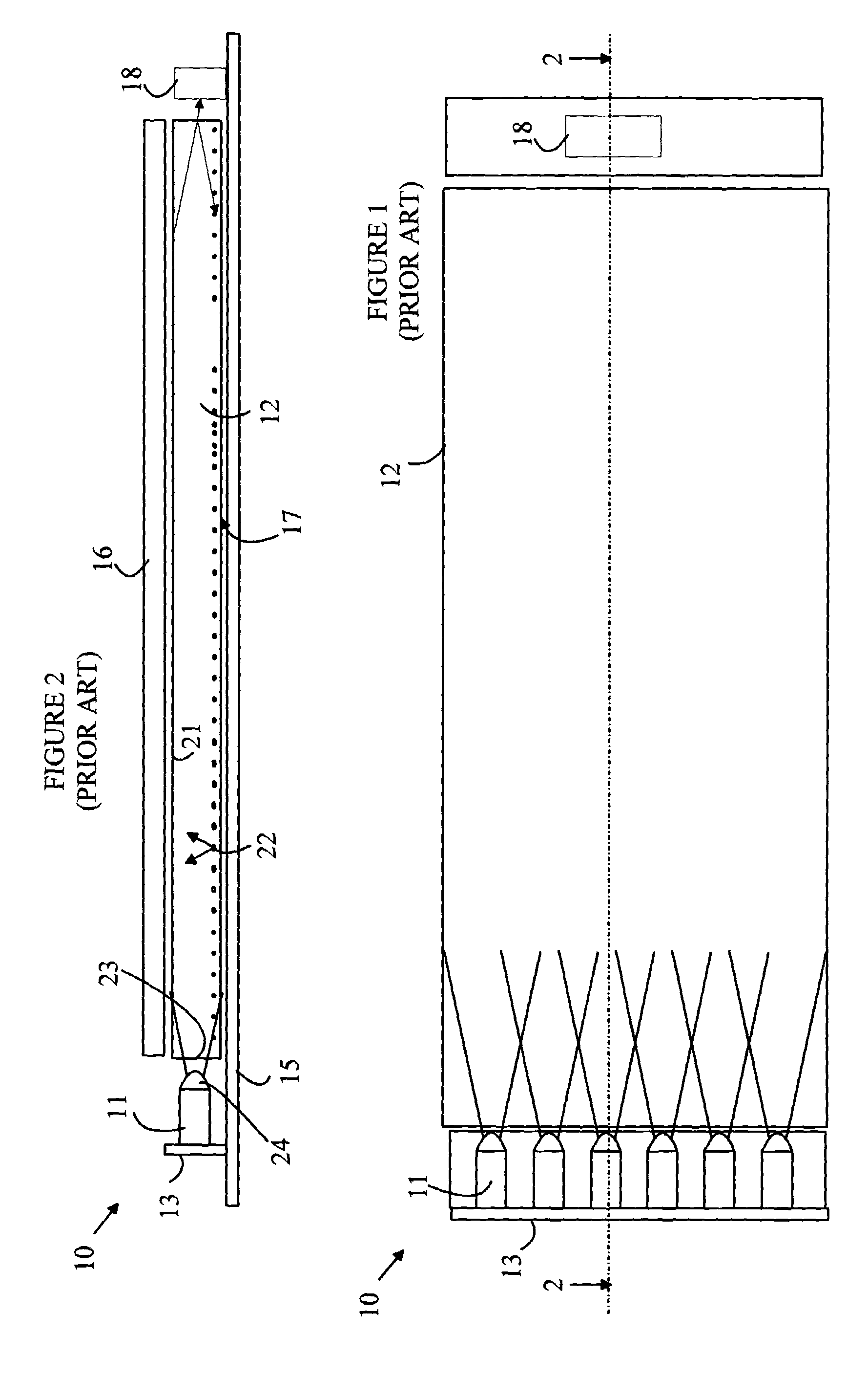
[0016]The manner in which the present invention provides its advantages can be more easily understood with reference to FIGS. 1 and 2, which illustrate a prior art light box arrangement for illuminating an LCD display 16. FIG. 1 is a top view of light source 10 and FIG. 2 is a cross-sectional view of light source 10 through line 2-2 shown in FIG. 1. Light source 10 utilizes an array of LEDs 11 to illuminate a light pipe 12. The LEDs are mounted on a circuit board 13 that is mounted on a second board 15 that provides power to the LEDs. The LEDs are positioned such that light leaving the top of each LED via lens 24 illuminates the end 23 of light pipe 12. The light entering light pipe 12 at an angle less than the critical angle with respect to surface 21 is reflected back and forth within light pipe 12 until the light is either absorbed or scattered by particles 22 on surface 17. The scattered light that strikes surface 21 at angles greater than the critical angle escapes from the lig...


PUM


Abstract

An apparatus having a light source, light pipe, and light conversion layer is disclosed. The light source includes a plurality of LED dies arranged in an array, each LED emitting light having an excitation wavelength, the light source emitting light within a cone of angles. The light pipe is positioned to receive the light within the cone of angles through an edge surface such that the light within the predetermined cone of angles is totally reflected from the top surface. The light pipe has features that redirect some of the light at angles such that some of the redirected light exits through the top surface. The light conversion layer overlies the top surface and converts light of the excitation wavelength to light in an output spectrum having wavelengths different from the excitation wavelength. A display layer can be placed such that it is illuminated by light from the light pipe.

Description

BACKGROUND OF THE INVENTION[0001]Liquid crystal displays (LCDs) are used in a wide variety of computers and consumer devices such as TVs. A back-lit LCD is an array of pixels in which each pixel acts as a shutter that either passes or blocks light from a light source that is located behind the pixel. Color displays are implemented by equipping the pixels with color filters such that each pixel transmits or blocks light of a particular color. The intensity of the light from each pixel is set by the time the pixel is in the transmissive state.[0002]The display is typically illuminated by a white light source that provides a uniform intensity of light across the back surface of the display. Illumination sources based on fluorescent lights are particularly attractive because of their high light output per watt-hour of power consumed. However, such sources require high driving voltages which makes them less attractive for battery operated devices.[0003]LCD displays for use in handheld de...

Claims


Application Information

Patent Timeline
Patent Type & Authority Patents(United States)
IPC IPC(8): F21V7/04H01J1/62
CPCB82Y20/00G02B6/0043G02B6/005G02F1/133603G02B6/0031G02F2202/36G02F1/133615G02F2001/133614G02B6/0068
Inventor CHUA, JANET BEE YINLAU, YUE HOONG
Owner TAIWAN SEMICON MFG CO LTD
Why Eureka
Try Eureka