
Low-cost circular polarizing eyewear

a circular polarizing and low-cost technology, applied in the field of circular polarizing eyewear, can solve the problems of increasing the overall cost of the circular polarizing materials, polarizing materials have to do with cost rather than performance, and the cost of the circular polarizing material is high compared to the more widely used linear polarizing material

Inactive Publication Date: 2009-04-14
REAID INC
View PDF5 Cites 55 Cited by
  • Summary
  • Abstract
  • Description
  • Claims
  • Application Information

AI Technical Summary

Problems solved by technology

Part of the reason for this lack of acceptance has been the high cost of circular sheet polarizer materials compared with the more widely used linear sheet polarizer.
A major commercial problem with regard to circular polarizing material has to do with cost rather than performance.
In some cases the device passes through a supplier or reseller, so there are many entities deriving profits from the sale of such devices, increasing the overall cost of the circular polarizer materials.
However, performance of linear polarizers is inferior for various reasons, including the Law of Malus, discussed below.
Moreover, recycled eyewear frequently become warped and scratched after on several cleanings.
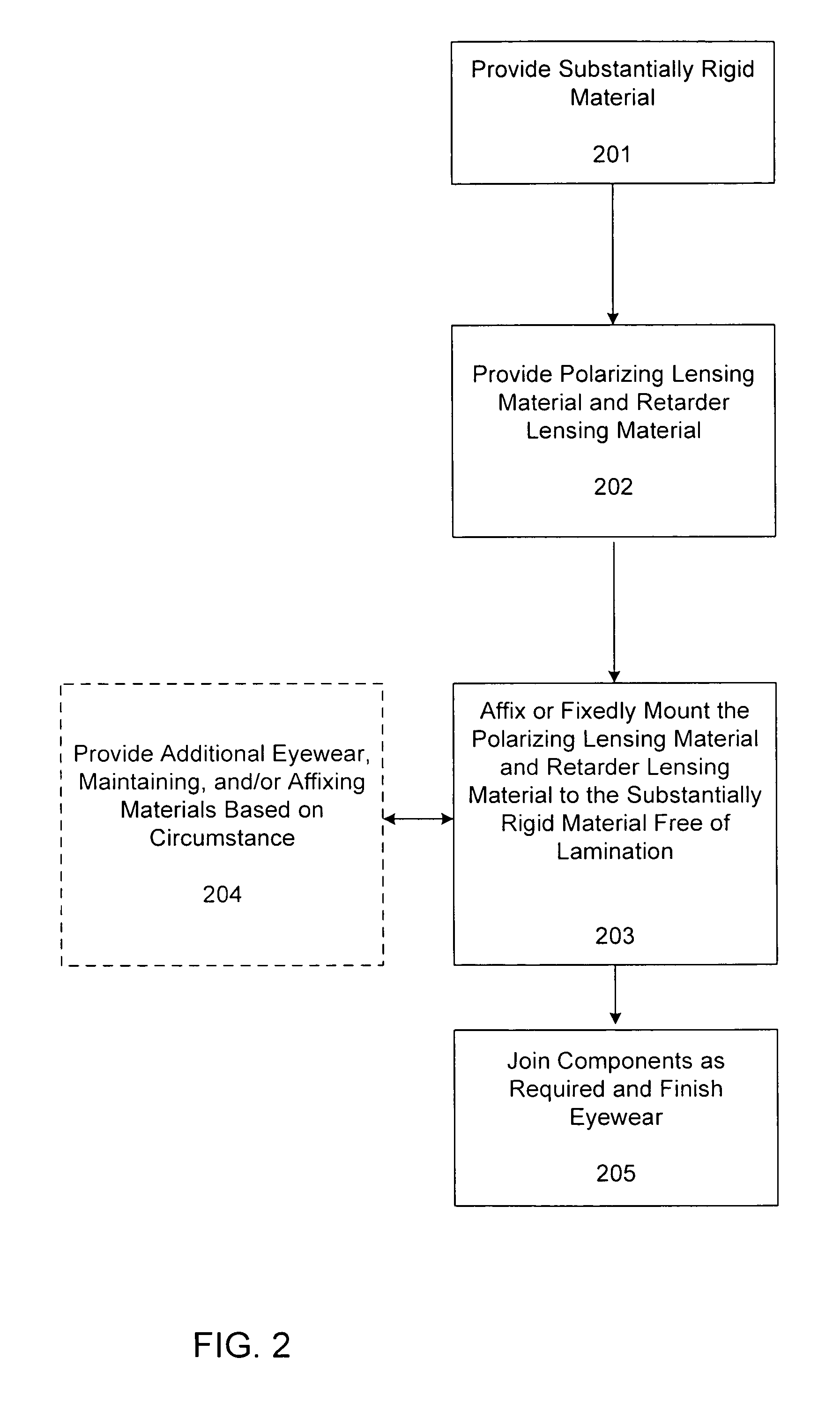
However, the costs involved include obtaining the polarizer material, obtaining the retarder material, laminating the polarizer material with the retarder material, and including the laminated polarizer and retarder material in the finished eyewear.
Each of these steps or processes takes time and money to complete.

Method used


Image

  • Low-cost circular polarizing eyewear
  • Low-cost circular polarizing eyewear
  • Low-cost circular polarizing eyewear

Examples


Embodiment Construction

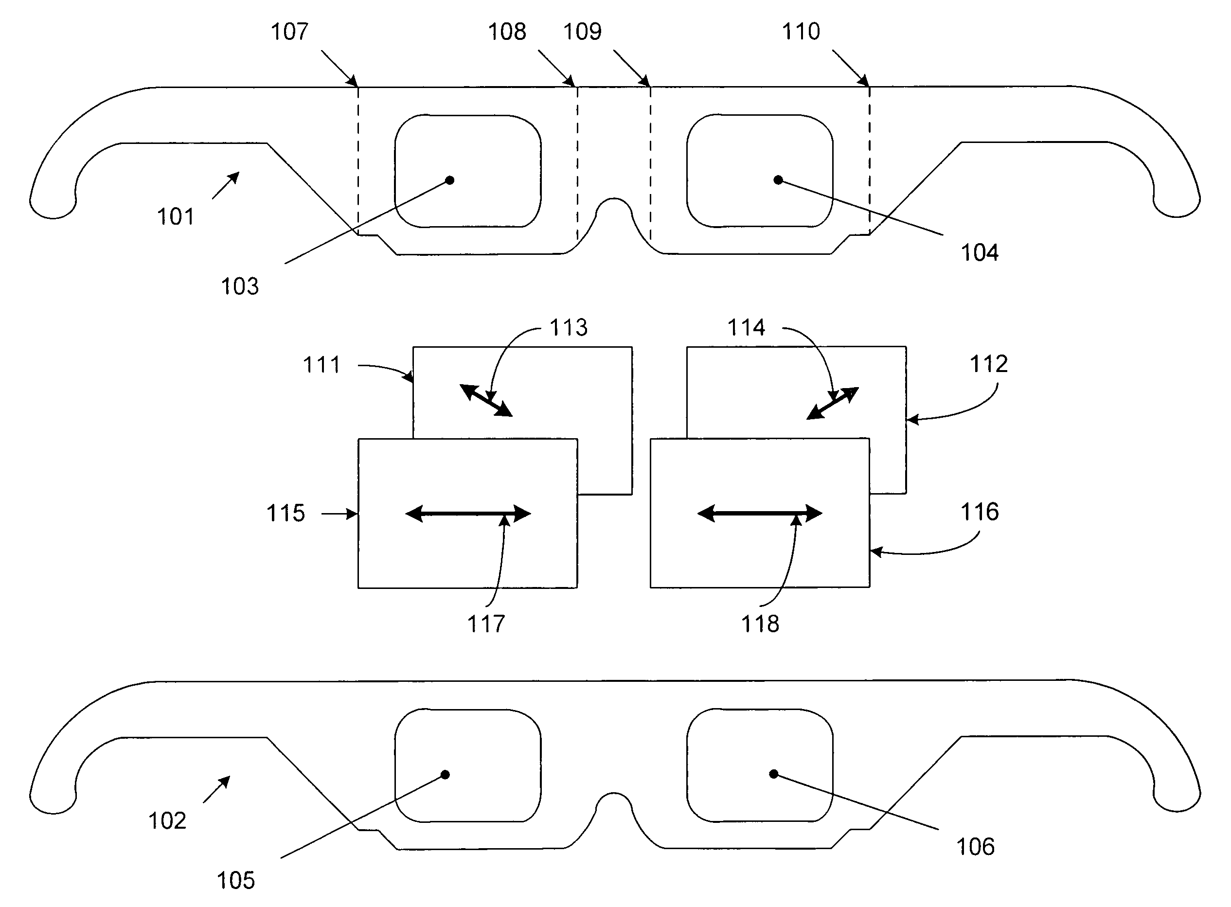
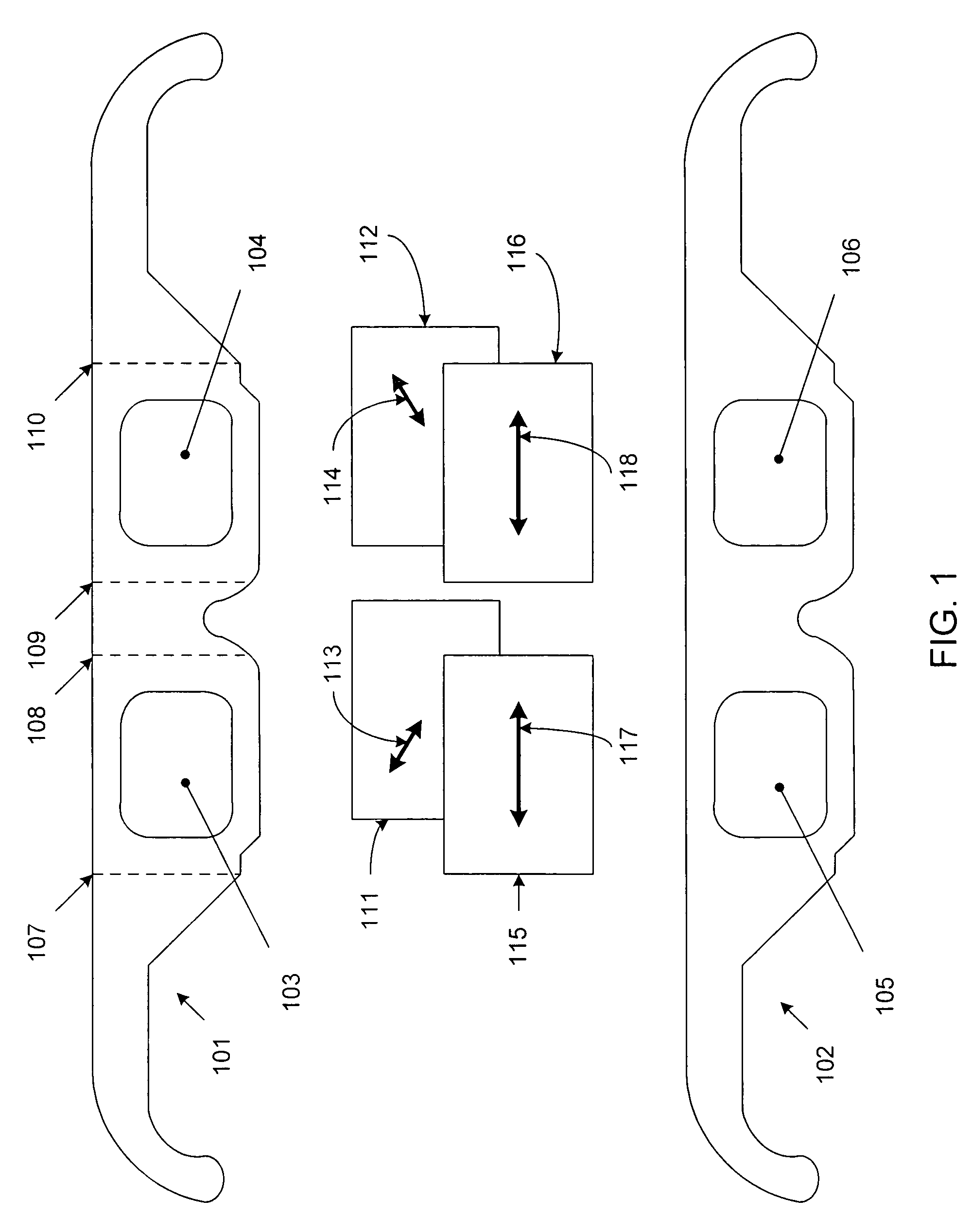
[0015]The present design does not use laminating of the retarder and polarizer, but instead merely employs the retarder and polarizer lensing materials in the stock or frames of the eyewear, thereby providing circularly polarized lenses in low cost eyewear that does not require lamination of the materials.

[0016]Previously available low cost eyewear typically employed linear polarizers, but such designs are not optimal for viewing stereoscopic images. When image selection uses linearly polarized light the Law of Malus applies. The Law of Malus relates the intensity I of linearly polarized light transmitted by a linear polarizer to both the intensity I0, of the incident linear polarized light and the angle B between the axis of incident polarized light and the axis of the analyzer. The relationship between these quantities is shown in Equation (1):

I=I0*cos2(B)  (1)

[0017]A small change in the angle B therefore results in a large change in transmission intensity. As a result, a small am...


PUM

PropertyMeasurementUnit
rigidaaaaaaaaaa
plasticaaaaaaaaaa
timeaaaaaaaaaa

Abstract

A method and system of providing circularly polarized eyewear is provided. The eyewear comprises substantially rigid material configured to maintain lensing material, such as card stock or plastic. The lensing material comprises polarizing lensing material located proximate the substantially rigid material, and retarder lensing material matched to the polarizing lensing material. The retarder lensing material is positioned adjacent to the polarizing lensing material such that each eye of a user sees an intended image, and an unintended image is blocked thereby when used in conjunction with suitably polarization encoded projected images. The polarizing lensing material and retarder lensing material are fixedly maintained in association with the substantially rigid material and are configured to be provided free of lamination.

Description

BACKGROUND OF THE INVENTION[0001]1. Field of the Invention[0002]The present design relates generally to the art of circular polarizing eyewear, and more specifically to enhanced techniques for cardboard, paper, plastic-framed or other kinds of eyewear that can lower the cost of providing circular polarizing eyewear for viewing projected stereoscopic motion pictures and maintaining the highest image quality.[0003]2. Description of the Related Art[0004]Circular polarized light for image selection has been the subject of several prior disclosures. Reference is made to the work of Land, U.S. Pat. No. 2,099,694, and Walworth in the proceedings of the SPIE, Vol. 462, Optics in Entertainment, “Three-Dimensional projection with Circular Polarizers.” Certain companies, including REAL D, the assignee of the present invention, project or release stereoscopic motion pictures in the theatrical cinema using circular polarization for image selection. Previously, for the most part, linear polarizat...

Claims


Application Information

Patent Timeline
Patent Type & Authority Patents(United States)
IPC IPC(8): G02C7/12
CPCG02B27/2228G02B27/26G02C7/12G02B30/25G02B30/34
Inventor LIPTON, LENNYARCHER, ROD
Owner REAID INC
Learn More