Method for real-time structure shape-sensing

a real-time structure and shape-sensing technology, applied in the direction of optical apparatus testing, force measurement by measuring optical property variation, instruments, etc., can solve the problem of inability to find a simple and straight forward approach to determine the out-of-plane structural displacemen

Inactive Publication Date: 2009-04-21
NAT AERONAUTICS & SPACE ADMINISTATION UNITED STATES OF AMERICA AS REPRESENTED BY THE DIRECTOR OF
View PDF6 Cites 59 Cited by
  • Summary
  • Abstract
  • Description
  • Claims
  • Application Information

AI Technical Summary

Problems solved by technology

Conversely, a simple and straight forward approach for determining the out-of-plane structural displacement is not available, especially for lightweight highly flexible and complex structures.

Method used


Image

  • Method for real-time structure shape-sensing
  • Method for real-time structure shape-sensing
  • Method for real-time structure shape-sensing

Examples


Embodiment Construction

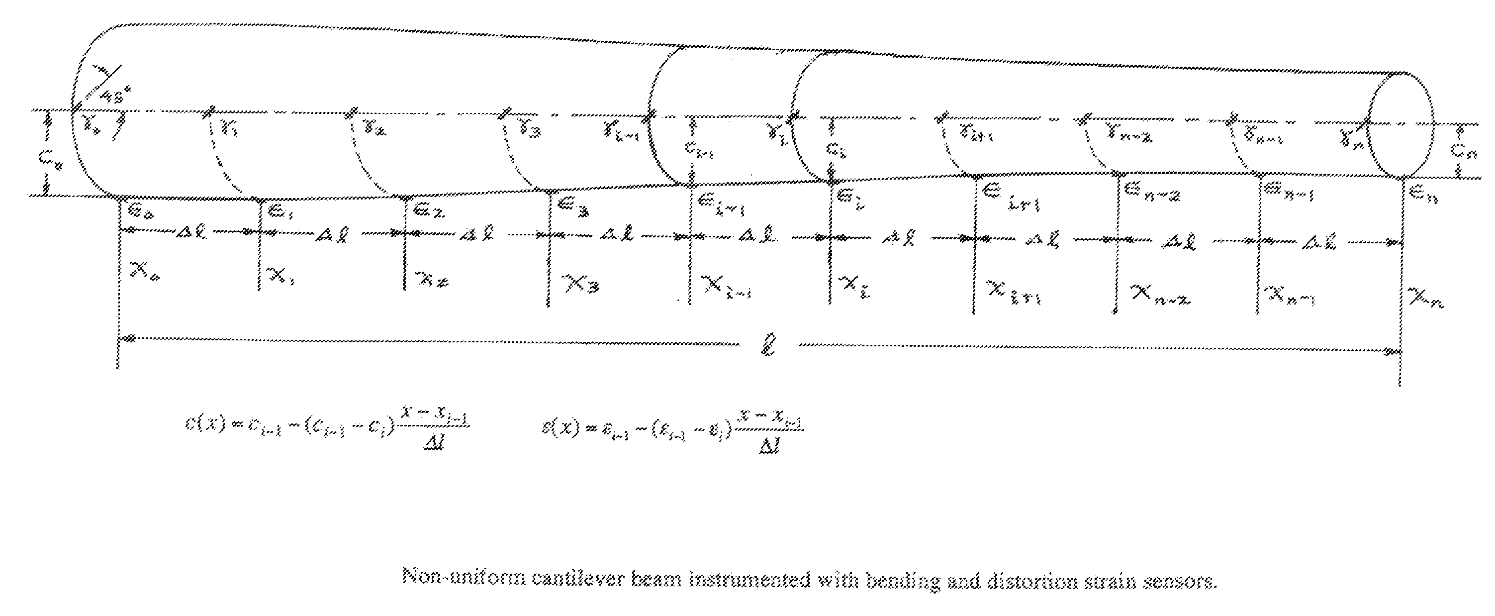
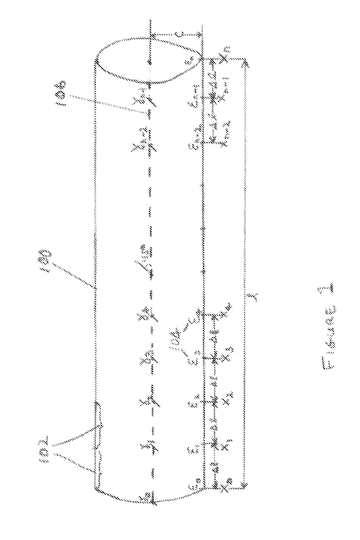
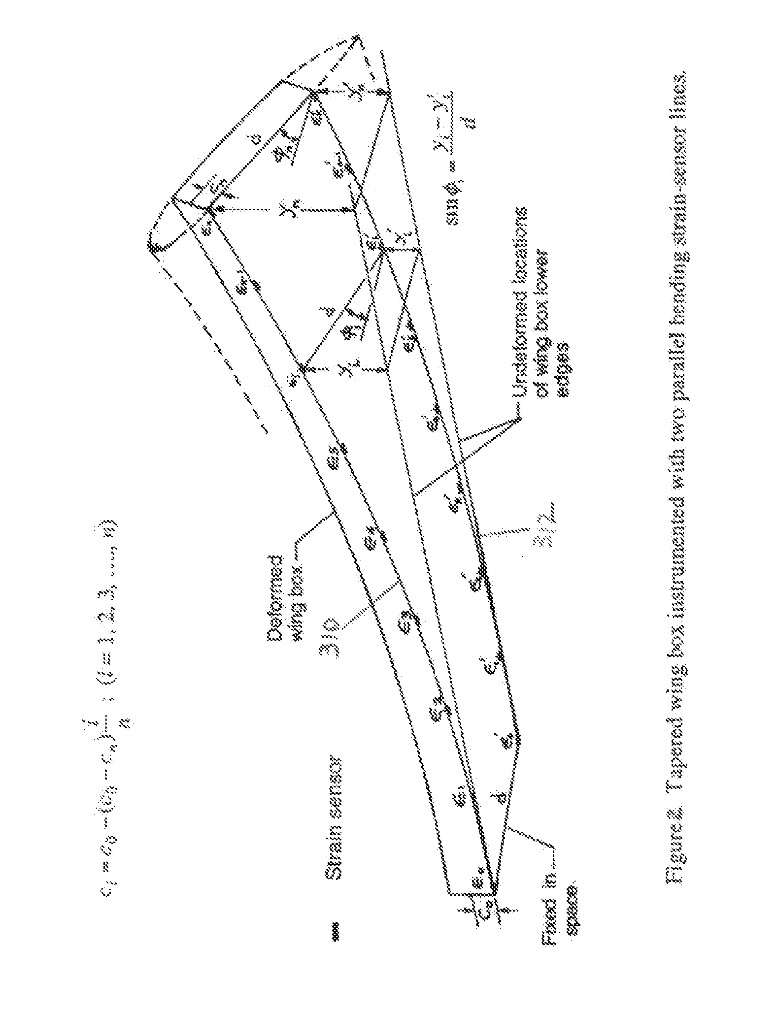
[0018]The invention, as embodied herein, comprises a method of obtaining displacement of a flexible structure by using strain measurements taken along the structure. For the present invention, the term displacement is defined as deformation of a structure out of the plane of the structure as applied to the structure's neutral axis. The term neutral axis is defined as the axis obtained by determining the axis or center point at each cross section of the structure.

[0019]Many technologies that employ flexible structures, particularly those that are relatively light-weight, can benefit from near real-time displacement data. These include high-aspect ratio flexible structures, aircraft wings (e.g. UAVs), rotocraft vehicles, space vehicles, wind turbine blades for the alternative energy community, space-based structures (booms and antenna), and long-span civil structures (bridges, dams). Since local strain is used as an input to the structural deformation method described herein, this met...


PUM

PropertyMeasurementUnit
lengthaaaaaaaaaa
lengthsaaaaaaaaaa
distanceaaaaaaaaaa

Abstract

The invention is a method for obtaining the displacement of a flexible structure by using strain measurements obtained by stain sensors. By obtaining the displacement of structures in this manner, one may construct the deformed shape of the structure and display said deformed shape in real-time, enabling active control of the structure shape if desired.

Description

STATEMENT OF GOVERNMENT INTEREST[0001]The invention described herein may be manufactured and used by or for the Government of the United States of America for governmental purposes without payment of any royalties thereon or therefor.BACKGROUND OF THE INVENTION[0002]1. Field of the Invention[0003]This invention relates in general to determining the deformed shape of complex structures using stain sensor measurements in real-time and more particularly to employing closed-form analytical solutions in conjunction with strain sensors to determine the deflection of complex structures of real-time.[0004]2. Description of the Related Art[0005]Resistive strain gauges have been employed for many years in experimental stress analysis in order to determine the stress-state produced in structures subjected to thermal and mechanical loads. More recently other sensors, such as those employing fiber optics, including fiber Bragg grating sensors, have also been used for the same purpose and for str...

Claims


Application Information

Patent Timeline
Patent Type & Authority Patents(United States)
IPC IPC(8): G01N3/00G01L1/24
CPCG01M5/0016G01M5/0041G01M5/0091G01M11/085
Inventor KO, WILLIAM L.RICHARDS, WILLIAM LANCE
Owner NAT AERONAUTICS & SPACE ADMINISTATION UNITED STATES OF AMERICA AS REPRESENTED BY THE DIRECTOR OF
Why Eureka
Try Eureka