
Horticulture light fixture having integrated lamp and ballast

a technology of light fixtures and ballasts, which is applied in the field of lighting systems for plants and agricultural purposes, can solve the problems of premature failure of lamps, premature failure of electronics located in close proximity to grow lamps, and heat generated by grow lamps

Active Publication Date: 2009-04-28
HGCI INC
View PDF6 Cites 138 Cited by
  • Summary
  • Abstract
  • Description
  • Claims
  • Application Information

AI Technical Summary

Benefits of technology

The integrated system effectively prevents premature failure of the lamp ballast by maintaining a thermal barrier, allowing for easy installation and extended longevity of both the grow lamp and ballast components.

Problems solved by technology

However, one significant drawback is the heat generated by these grow lamps.
Without cooling, the lamps will prematurely fail.
Due to the extreme heat, any electronics located in close proximity to the grow lamp will also prematurely fail.
Lamp ballasts suffer from temperature sensitivity in that excessive temperatures cause premature failure of the electronic components, leading to decreased performance.
Previously integrating the lamp ballast into the horticulture light fixture was not feasible due to the high temperatures generated by the grow lamp and the relatively low temperature failure rates of the ballast.
If installed too close to the grow lamp, the lamp ballast will fail prematurely due to the heat produced by the lamp and absorbed by the ballast.
Prior attempts to integrate the lamp ballast into the horticulture light fixture have failed because excessive heat produced by the grow lamp was absorbed by the lamp ballast, causing premature failure of the lamp ballast.
Lamp ballasts are sensitive to heat; and, as the operating temperature increases, performance and longevity decrease.

Method used


Image

  • Horticulture light fixture having integrated lamp and ballast
  • Horticulture light fixture having integrated lamp and ballast
  • Horticulture light fixture having integrated lamp and ballast

Examples


Embodiment Construction

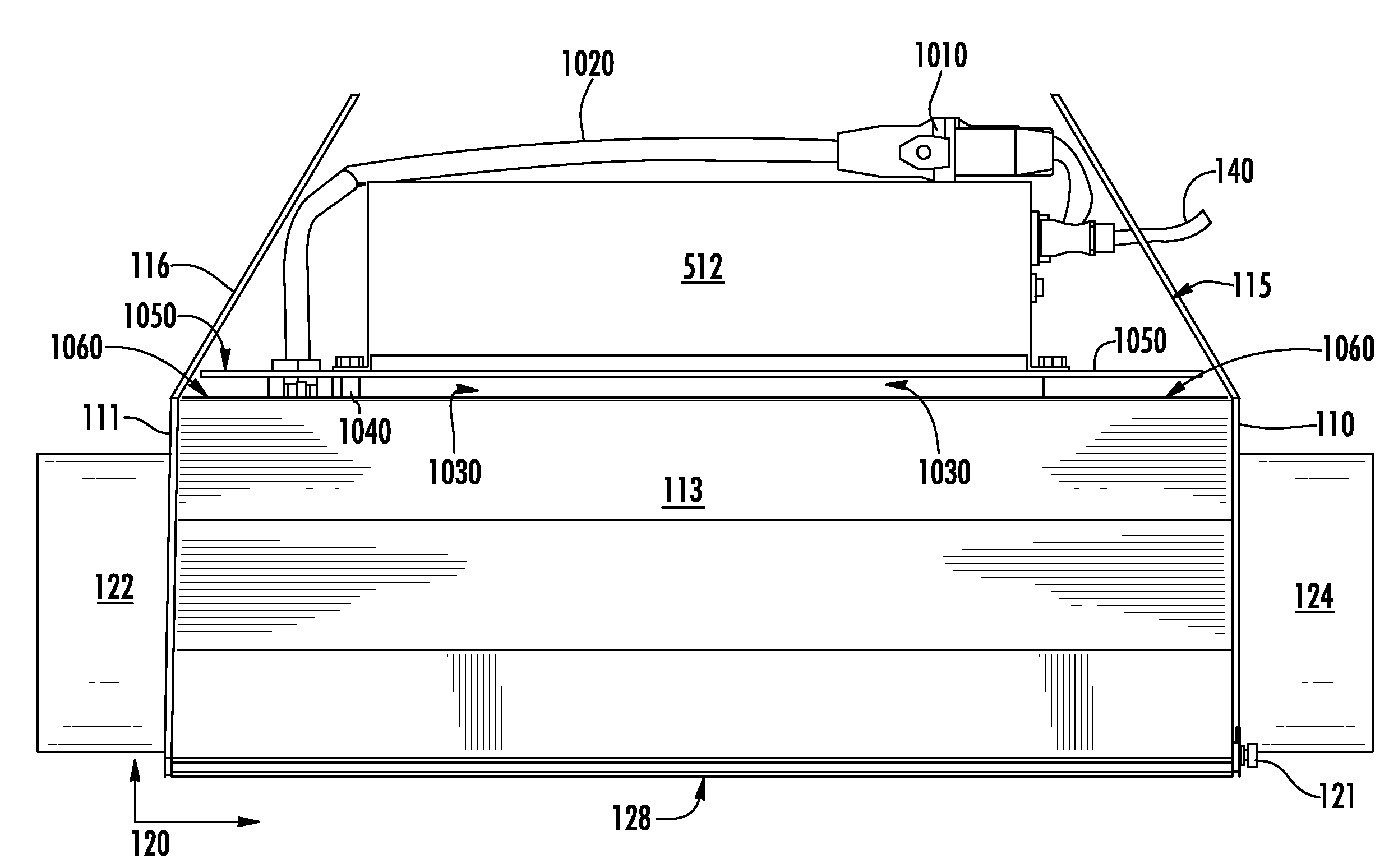
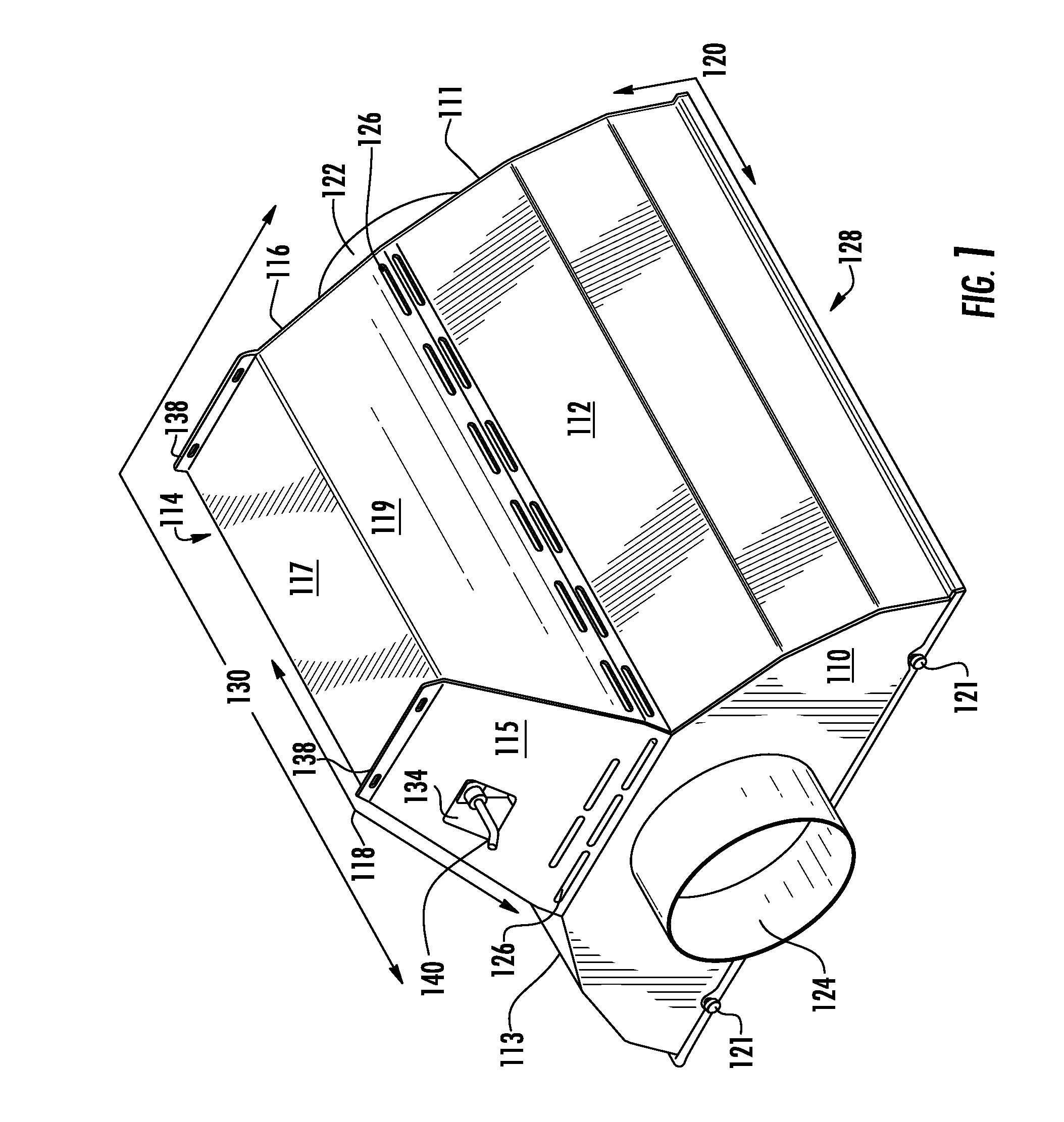
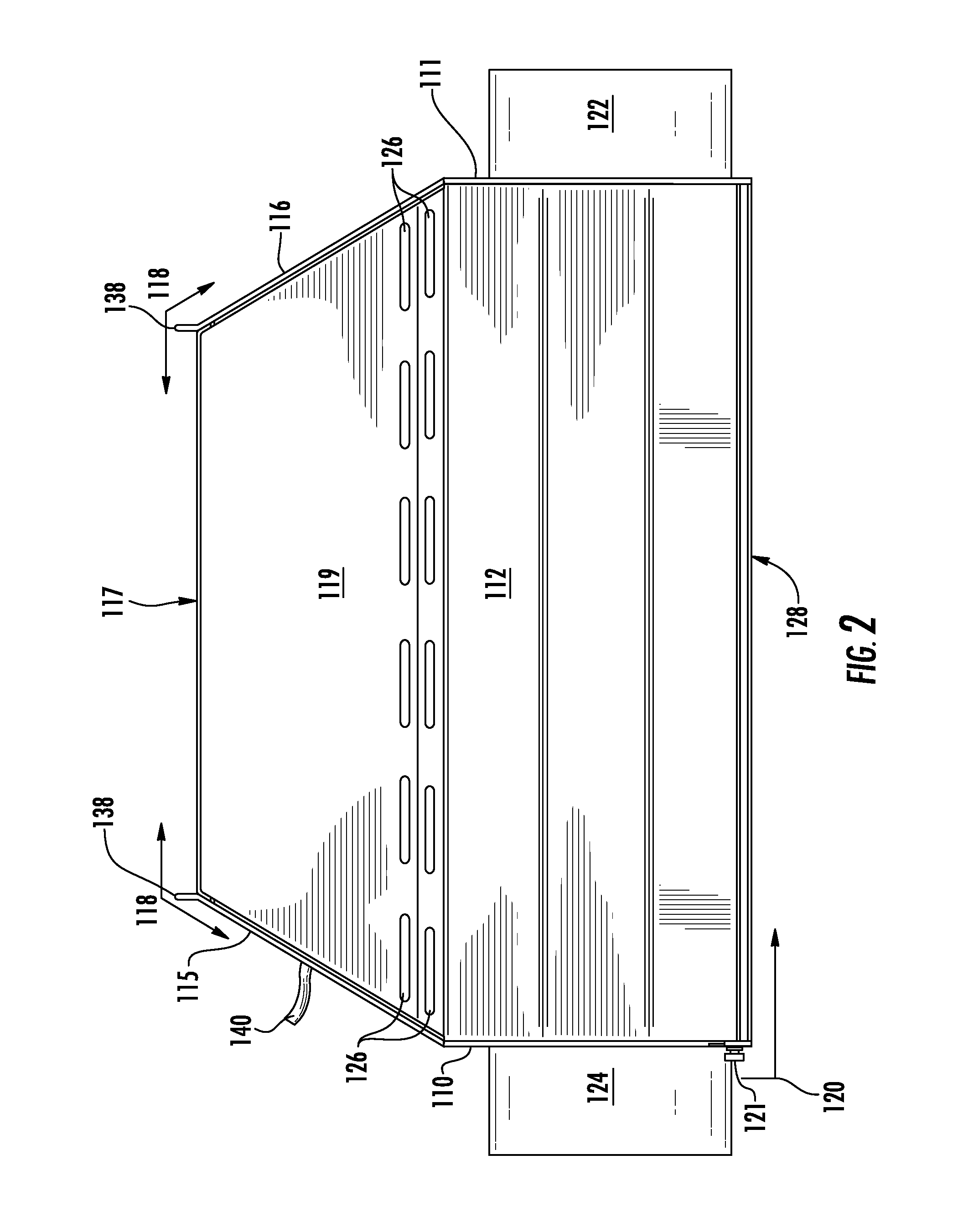
[0030]Referring now to the drawings, and particularly to FIGS. 1-10, a preferred embodiment of the present device is shown, illustrating the horticultural and agricultural lighting systems used in developing plants in controlled growing environments. The exemplary embodiments according to the present device are illustrated with those components necessary to demonstrate the inventive design. Many of the necessary electrical and mechanical elements for attaching, powering, and implementing are not present. For example, the electrical service connection of 110 volts or 220 volts is known by one of normal skill in the art but not specifically mentioned. The horticulture lamp types most commonly used are high pressure sodium and metal halide—both high intensity discharge and requiring specific power that is well known by one of ordinary skill in the art. Elements not present or described below may take on any known form consistent with forms readily realized by one of ordinary skill in t...


PUM


Abstract

A horticultural light system integrating a grow lamp and lamp ballast within a single fixture. The grow lamp is enclosed by the lower exterior structure and benefits from cooling atmosphere that is forced through the lower exterior structure to regulate the grow lamp temperature. The lamp ballast is mounted to a ballast plate above the lower exterior structure. The ballast plate shields the lamp ballast from the heated atmosphere as it rises off the top of the lower exterior structure. Stand offs or other separation means keep the ballast plate at a distance from the top of the lower exterior structure to create an air gap that thermally isolates the lamp ballast from the heat generated by the grow lamp, thereby increasing the reliability and life of the lamp ballast.

Description

CROSS REFERENCES TO RELATED APPLICATIONS[0001]NoneSTATEMENT REGARDING FEDERALLY SPONSORED RESEARCH OR DEVELOPMENT[0002]This invention is not the product of any Federally Sponsored Research or Development.REFERENCE TO MICROFICHE APPENDIX[0003]Not ApplicableBACKGROUND OF THE INVENTION[0004]1. Technical Field[0005]The present device relates generally to horticultural and agricultural lighting systems used in developing and growing plants in controlled environments.[0006]2. Discussion of Related Art[0007]Indoor gardens, green houses, hydroponics systems, and isolated carbon dioxide growing chambers demand careful regulation of temperature, light, hydration, nutrients, and humidity. In these controlled environments the grower must provide adequate light intensity, which is usually accomplished using an HID grow lamp in cooperation with a remote HID lamp ballast that is located within a couple feet of the HID grow lamp.[0008]The most common HID grow lamps are high pressure sodium and meta...

Claims


Application Information

Patent Timeline
Patent Type & Authority Patents(United States)
IPC IPC(8): F21V29/00
CPCA01G7/045F21V23/026A01G9/249Y10S362/805Y02P60/14
Inventor HARGREAVES, CRAIG
Owner HGCI INC
Learn More