Two-piece optical lens system for taking image

a two-piece optical lens and image technology, applied in the field of two-piece optical lens systems for taking images, can solve the problems of the cost of the first lens element made of glass, the incident angle of the optical lens system will get worse, and the incident angle of the optical lens system can still be slightly poor

Active Publication Date: 2009-04-28
LARGAN PRECISION
View PDF2 Cites 92 Cited by
  • Summary
  • Abstract
  • Description
  • Claims
  • Application Information

AI Technical Summary

Problems solved by technology

And the researchers are also required to design the optical lens system consisting of two lens elements, but such an optical lens system has a main problem, that is, the characteristic of an incident angle of the optical lens system will get worse.
However, the slightly poor characteristic of the incident angle of the optical lens system can still be used in the micro-lens elements of the solid image sensor such as CCD or CMOS.
The disadvantages of the above patents lie in:
The cost of the first lens element made of glass of Japan Pat. No. 1 is high, and the refractive power of the second lens element is too weak, so that the chromatic aberration will not be sufficiently corrected.
The first and second lens elements of Japan Pat. Nos. 2 and 4 are made of the same material, so that the chromatic aberration will not be sufficiently corrected, and the high optical performance can not be ensured.
The second lens element of Japan Pat. No. 3 is a negative lens element has a convex object-side surface, the concave image-side surface is difficult to manufacture, and the peripheral edge of the second lens element leans to the image side, so that the back focal length can not be ensured.

Method used


Image

  • Two-piece optical lens system for taking image
  • Two-piece optical lens system for taking image
  • Two-piece optical lens system for taking image

Examples


first embodiment

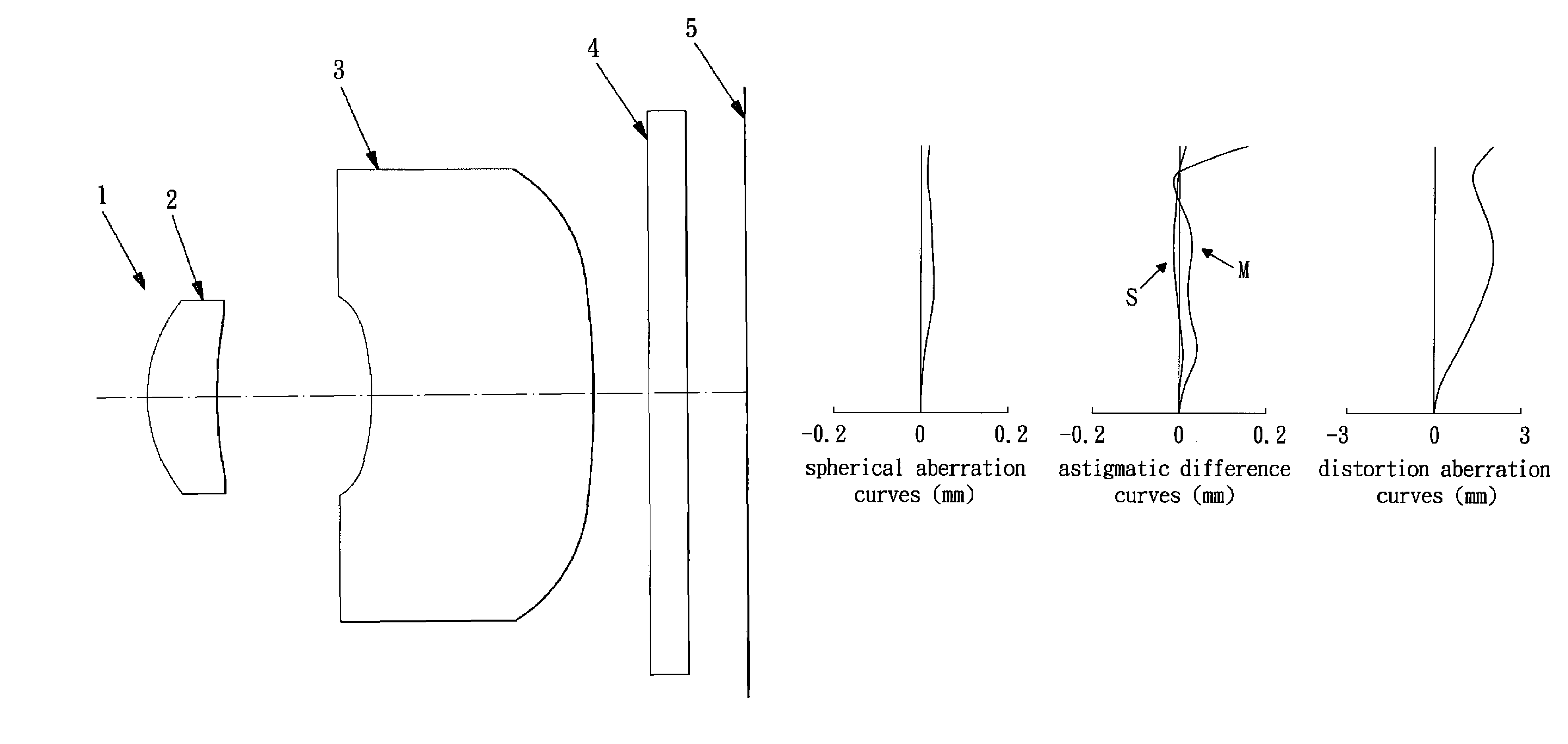
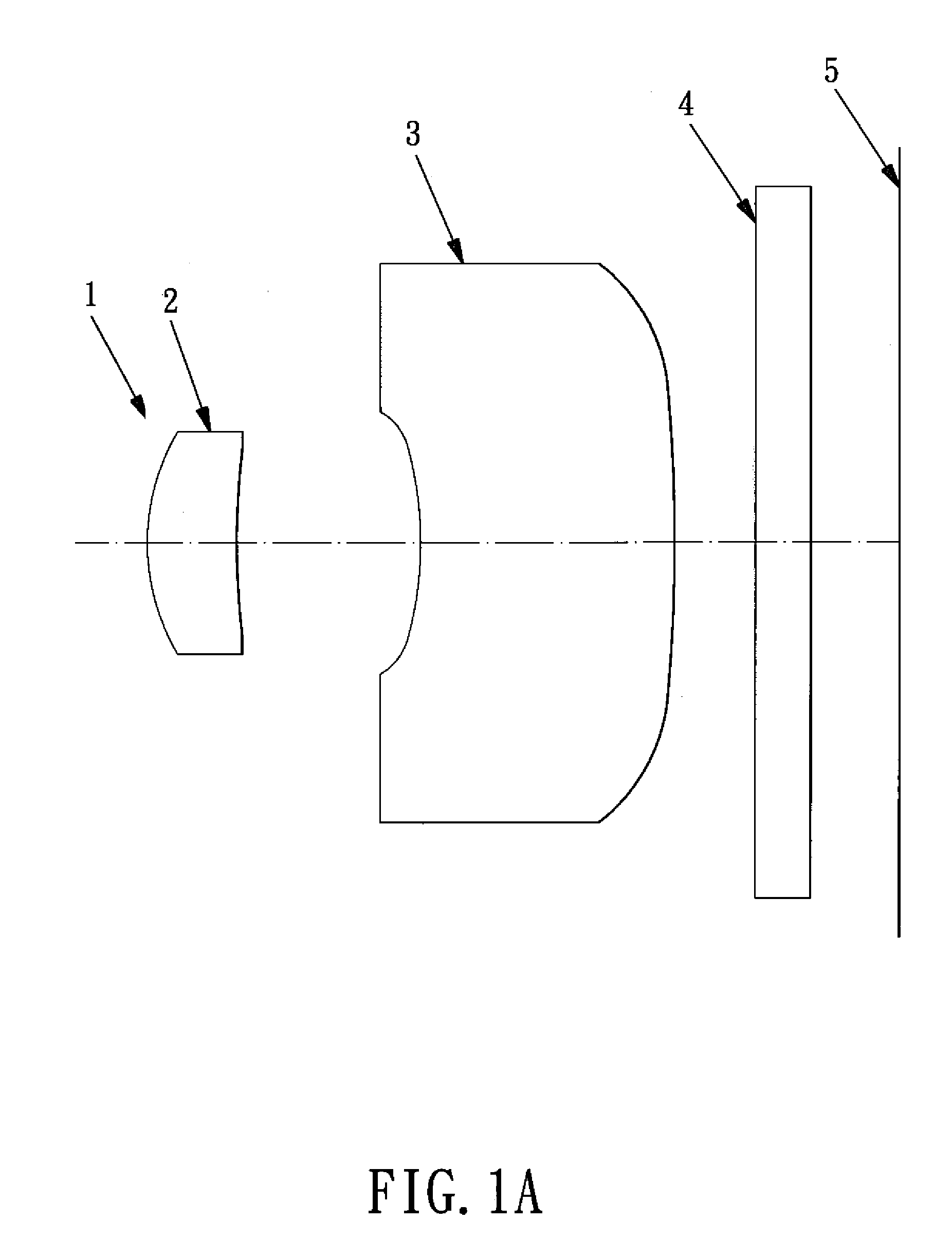
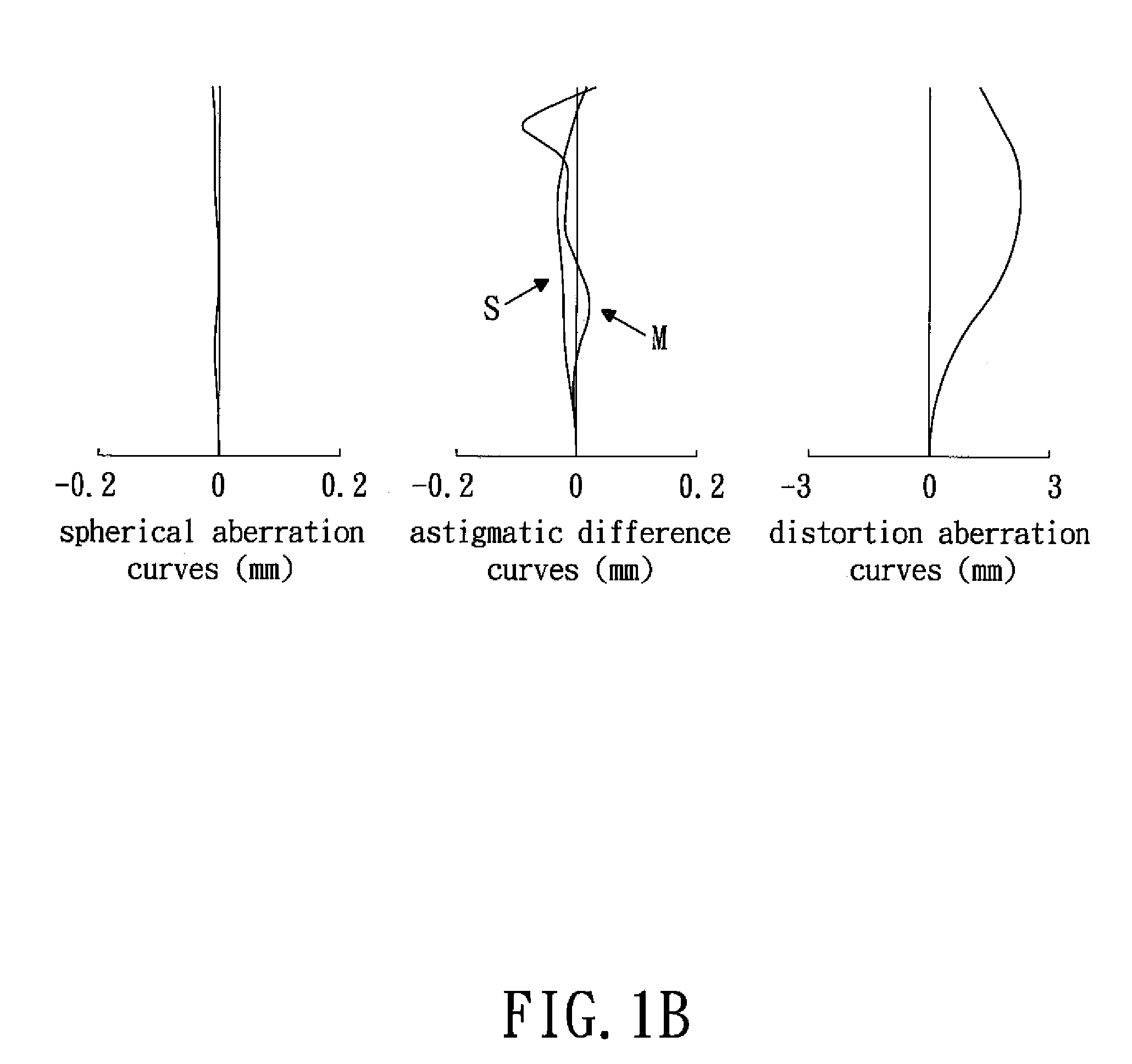
[0063]In the present optical lens system for taking image:

[0064]the focal length of the optical lens system for taking image is f, and F=4.00 mm

[0065]Fno.=3.21

[0066]field of view 2ω=59.1°

[0067]Referring to table 1A, the Arabic numbers 1, 2, . . . 6 represent the sequence number of the surfaces of the first lens element 2, the second lens element 3, and the parallel flat glass 4 from the object side. The r represents the paraxial radius of curvature (its unit is mm); d represents the thickness of the lens elements (its unit is mm); nd means the refractive index and νd means Abbe number. Numbers 5 and 6 represent both sides of the parallel flat glass 4 whose radius of curvature r is ∞. And all the embodiments of the present invention are the same in this point.

[0068]Table 1B shows the aspherical coefficients, the above surfaces of each lens element are aspheric. The aspherical coefficients of the respective lens elements are indicated by A, B, C, D and E, the height of the optical axi...

second embodiment

[0072]In the present optical lens system for taking image:

[0073]the focal length of the optical lens system for taking image is f, and f=4.62 mm

[0074]Fno.=2.92

[0075]field of view 2ω=56.0°

[0076]table 2A shows each component of the optical lens system, and table 2B shows the aspherical coefficient.

[0077]

TABLE 2ArDndνdAperture Stop∞0.00011.35620.5641.5434056.525.03551.2393−2.75961.8281.6320023.44−9.84180.4495∞0.3001.5168064.26∞0.488

[0078]

TABLE 2BSur-face#1234K =1.29242E−013.15006E−01−3.21073E−01−7.86269E+00A =−9.08382E−042.70775E−02−1.91369E−01−2.08962E−02B =−9.27818E−02−3.35055E−023.72625E−01−9.83922E−03C =6.37964E−01−1.38815E−01−2.20644E+006.10556E−03D =−2.50149E+004.33982E−016.22376E+00−4.02529E−03E =5.15472E+003.42007E−01−1.17844E+011.51404E−03

third embodiment

[0079]In the present optical lens system for taking image:

[0080]the focal length of the optical lens system for taking image is f, and f=3.14 mm

[0081]Fno.=3.22

[0082]field of view 2ω=58.1°

[0083]table 3A shows each component of the optical lens system, and table 3B shows the aspherical coefficient.

[0084]

TABLE 3ArdndνdAperture Stop∞0.00010.80610.4951.5434056.521.54230.7873−3.70960.7741.6320023.44−352.55980.2535∞0.5001.5168064.26∞0.400

[0085]

TABLE 3BSur-face#1234K =5.61761E−012.97022E−01−1.88710E+011.00000E+00A =−4.39698E−023.24764E−01−4.33358E−01−1.35113E−01B =−9.60236E−015.16416E−012.18731E−01−1.66172E−01C =9.73796E+002.85387E+00−1.59626E+013.39366E−01D =−7.15122E+01−1.75796E+011.40289E+02−3.16976E−01E =2.96511E+022.60540E+02−5.88477E+024.94315E−02


PUM


Abstract

A two-piece optical lens system for taking image comprises, from the object side: a first lens element and a second lens element. The first lens element is a positive meniscus lens element has a convex object-side surface. The second lens element is a negative meniscus lens element has a convex image-side surface. Both the object-side surface and the image-side surface of the first and second lens elements are aspheric, the first and second lens elements are made of plastic material, and they satisfy the relations: 0.55<f1 / f<0.95, −2.0<f2 / f<−1.0, 27.0<ν1−ν2. The focal length of the optical lens system is f, the focal length of the first lens element is f1, the focal length of the second lens element is f2, the Abbe number of the first lens element is ν1, and the Abbe number of the second lens element is ν2.

Description

BACKGROUND OF THE INVENTION[0001]1. Field of the Invention[0002]The present invention relates to a two-piece optical lens system for taking image, and more particularly to a miniaturized two-piece optical lens system for taking image used in a mobile phone camera.[0003]2. Description of the Prior Art[0004]The present invention relates to an optical lens system for taking image, from the object side comprises: an aperture stop, a first lens element and a second lens element, which is particularly suitable for use in the miniaturized portable machines with a high optical performance.[0005]With the price coming down, the high resolution (1-3 million pixels) mobile phone cameras are usually made up of three lens elements. And the researchers are also required to design the optical lens system consisting of two lens elements, but such an optical lens system has a main problem, that is, the characteristic of an incident angle of the optical lens system will get worse.[0006]However, the sl...

Claims


Application Information

Patent Timeline
Patent Type & Authority Patents(United States)
IPC IPC(8): G02B9/04G02B13/18G02B3/06
CPCG02B13/003G02B13/18
Inventor NODA, SAYURI
Owner LARGAN PRECISION
Why Eureka
Try Eureka