Plasma television, flat panel display fixing structure, flat panel television, and method of assembling flat panel television

a flat panel display and fixing structure technology, applied in the field of plasma televisions, can solve the problems of affecting the normal operation the deformation or otherwise deformation of the television cabinet, and the load applied to the television cabinet, so as to prevent the deformation of the cabinet, prevent the transmission of a load to the plasma display panel, and prevent the effect of the own weight of the flat panel display on the cabin

Inactive Publication Date: 2009-05-05
FUNAI ELECTRIC CO LTD
View PDF18 Cites 40 Cited by
  • Summary
  • Abstract
  • Description
  • Claims
  • Application Information

AI Technical Summary

Benefits of technology

[0016]The present invention has been made in view of the above problems and an object of the present invention is to provide, at low cost, a plasma television and a flat panel display fixing structure which enable maintaining a prescribed positional relationship between a flat panel display and members for supporting the flat panel display even in a case where different makes of the flat panel displays are used.
[0017]Another object of the present invention is to provide a plasma television, a flat panel television, and a flat panel television assembly method which can prevent a cabinet from becoming defective and which can protect a flat panel display.

Problems solved by technology

Therefore, in a case where different makes of the flat panel displays 1 are used in assembling televisions, it has been difficult to uniformize the positional relationship between the flat panel display 1 and the brackets 4.
As described above, a problem with the conventional techniques is that the weight of a flat panel display causes a television cabinet to be subjected to a large load eventually causing the television cabinet to be deformed or otherwise become defective.
There has also been another problem that a load applied to a television cabinet from the outside can be easily transmitted to a flat panel display which is a precision device accommodated in the television cabinet.

Method used


Image

  • Plasma television, flat panel display fixing structure, flat panel television, and method of assembling flat panel television
  • Plasma television, flat panel display fixing structure, flat panel television, and method of assembling flat panel television
  • Plasma television, flat panel display fixing structure, flat panel television, and method of assembling flat panel television

Examples


Embodiment Construction

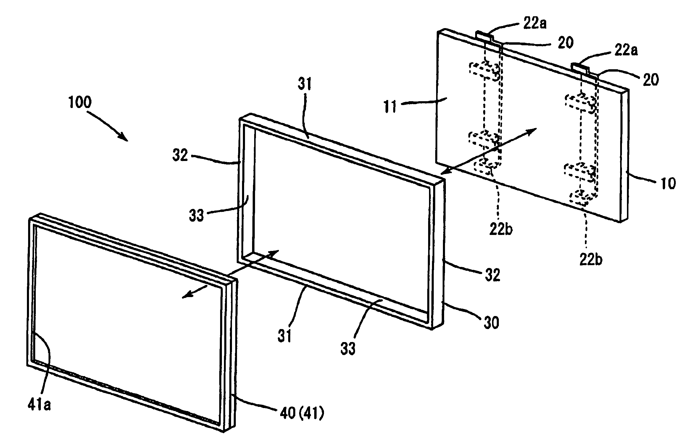
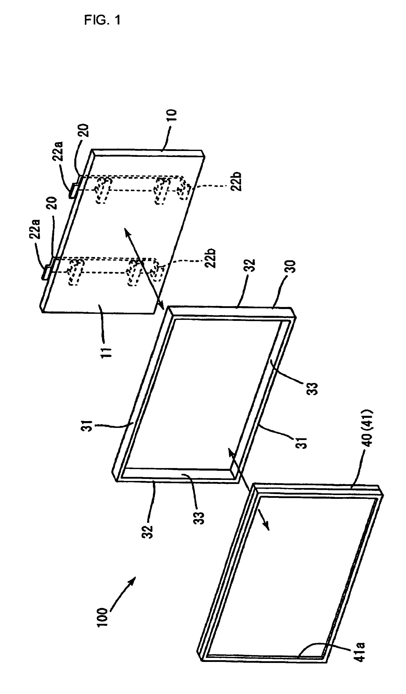
[0085]FIG. 1 is a perspective view of a plasma television assembly according to the present invention.

[0086]Though the mode of television assembly according to the present invention is applicable to flat-screen screen televisions in general including liquid crystal televisions, the present embodiment will be explained based on a case of assembling a plasma television.

[0087]As shown in FIG. 1, a plasma television 100 is, described roughly, an assembly of a plasma display panel (PDP) 10, a frame 30, and a cabinet 40. The cabinet 40 includes a front cabinet 41 and a rear cabinet not shown in FIG. 1. There is an opening 41a formed at about the center of the front of the front cabinet 41. The PDP 10 is installed in the cabinet 40, with a display surface 11 facing the opening 41a.

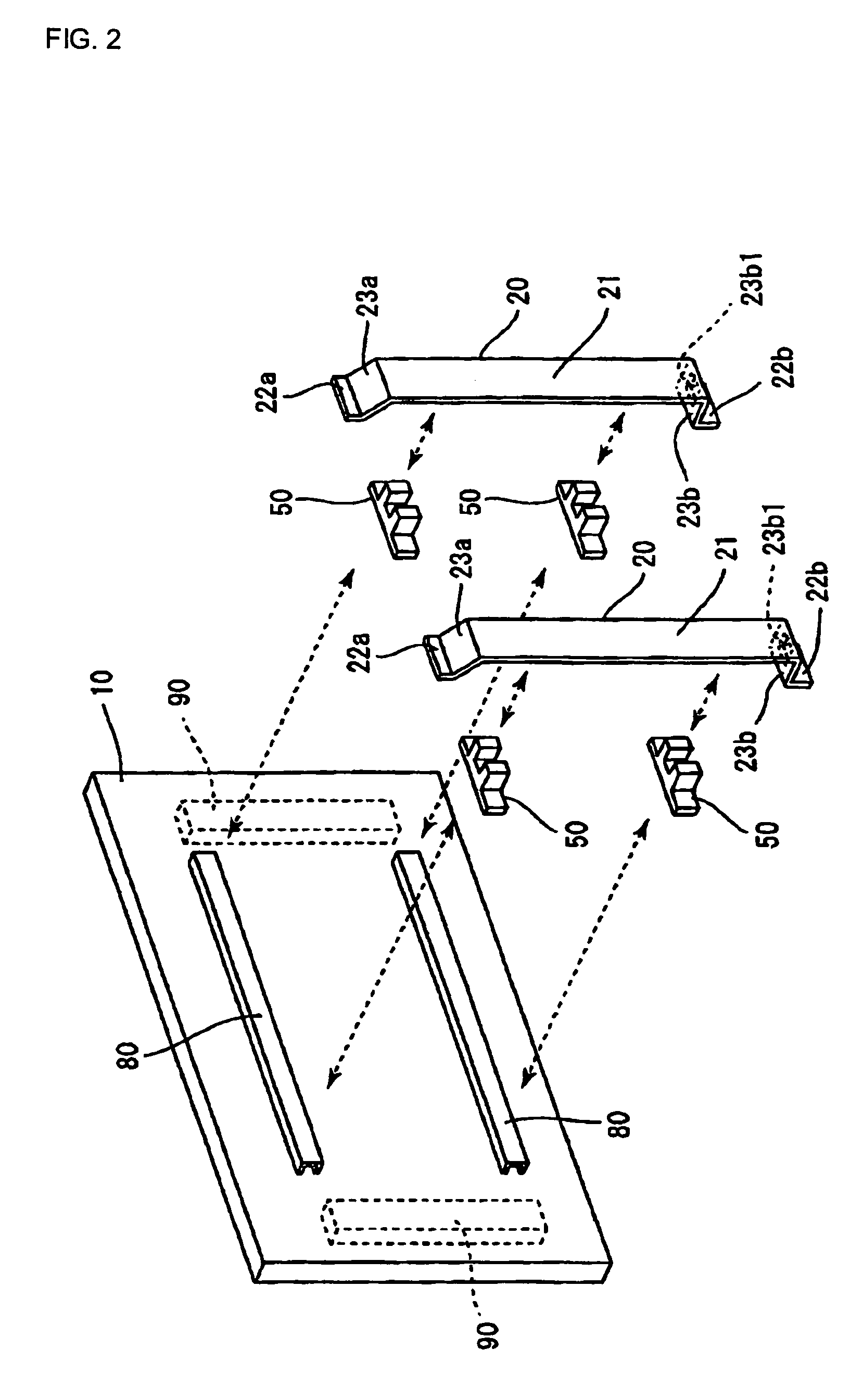
[0088]In the present embodiment, first, the PDP 10 is fixed, at prescribed locations on its back, to brackets 20. How the PDP 10 is fixed to the brackets 20 will be described later. Next, the brackets 20 holding...


PUM


Abstract

Each of attachments 50 has fixtures formed in a base part 51 for fixation to metal fixtures 80a and 80b. It also has a projecting part 52 having two surfaces formed on its side which opposes one of brackets 20. The two surfaces differ in height by an amount corresponding to the difference in height between the metal fixtures 80a and 80b. Each of the two surfaces has a fixture formed thereon. The brackets 20 each have screw holes and clearance holes formed in their portions which oppose, when their vertical locations relative to PDP 10a and PDP 10b are kept unchanged, the attachments 50 fixed to the metal fixtures 80a and 80b, respectively.

Description

BACKGROUND OF THE INVENTION[0001]1. Field of the Invention[0002]The present invention relates to a plasma television, a flat panel display fixing structure, a flat panel television, and a method of assembling a flat panel television.[0003]2. Description of the Prior Art[0004]FIG. 10 shows a conventional arrangement in which a flat panel display such as a plasma display panel is fixed to prescribed supporting members.[0005]In FIG. 10, the back side of a flat panel display 1 is shown. The flat panel display 1 is, at its back, fixed to two brackets 4 (shown in two-dot chain lines) used as supporting members. To be more concrete, each of the brackets 4 is connected to the flat panel display 1 via connecting members 3 which are fixed in an upper and a lower location on each of the left-hand and the right-hand sides of the back of the flat panel display 1. The connecting members 3 are fixed, to be apart from each other by a prescribed distance, to fixing members 2 which, each having a pre...

Claims


Application Information

Patent Timeline
Patent Type & Authority Patents(United States)
IPC IPC(8): H05K5/00G06F1/16H05K7/00A47G1/24B60R1/02
CPCG06F1/16G06F1/1601Y10S248/917Y10S248/918Y10S248/919Y10S248/924
Inventor MARUTA, NAOTO
Owner FUNAI ELECTRIC CO LTD
Why Eureka
Try Eureka