Hand shake blur detecting apparatus

a detection apparatus and hand shake technology, applied in the field of hand shake blur detection apparatus, can solve the problems of incomplete electronic hand shake blur correction technique, image has not reached the practical level, and the technique of generating images has not been applied in the practical level, and achieves the effect of high precision hand shake blur signal

Inactive Publication Date: 2009-05-05
XACTI CORP
View PDF9 Cites 4 Cited by
  • Summary
  • Abstract
  • Description
  • Claims
  • Application Information

AI Technical Summary

Problems solved by technology

The completely electronic hand shake blur correction technique, that is, a technique of generating the image in which hand shake blur is removed by analyzing and processing only one photographed hand shake blur image has not reached the practical level.
In particular, obtaining a hand shake blur signal of a precision obtained by a hand shake blur sensor is difficult by analyzing one hand shake blur image.
However, when the detecting section of the hand shake blur detecting apparatus is miniaturized, the drift or offset component is added to the output signal due to change in temperature of the environment or rise in temperature caused by the use of the element itself, and the output precision lowers.
Further, if the cut-off frequency of the HPF is reduced, the time constant becomes large, and a long stable period becomes necessary to clear the residual component of the hand shake blur, and thus the stop state over a long period of time is necessary before shooting.
However, the offset component (DC component) that is difficult to measure is included when changing the time constant of the HPF.
In Japanese Laid-Open Patent Publication No. 4-68322, a technique of giving a warning or prohibiting release until the output of the sensor stabilizes is proposed, but the photo opportunity may be missed.
However, in this technique, the residual component cannot be removed if the input signal of the HPF does not become 0 after the generation of large residual component.

Method used


Image

  • Hand shake blur detecting apparatus
  • Hand shake blur detecting apparatus
  • Hand shake blur detecting apparatus

Examples


Embodiment Construction

[0039]An example of applying the present invention to a digital camera will now be described with reference to the figures.

[1] Configuration of Hand Shake Blur Correction Processing Circuit

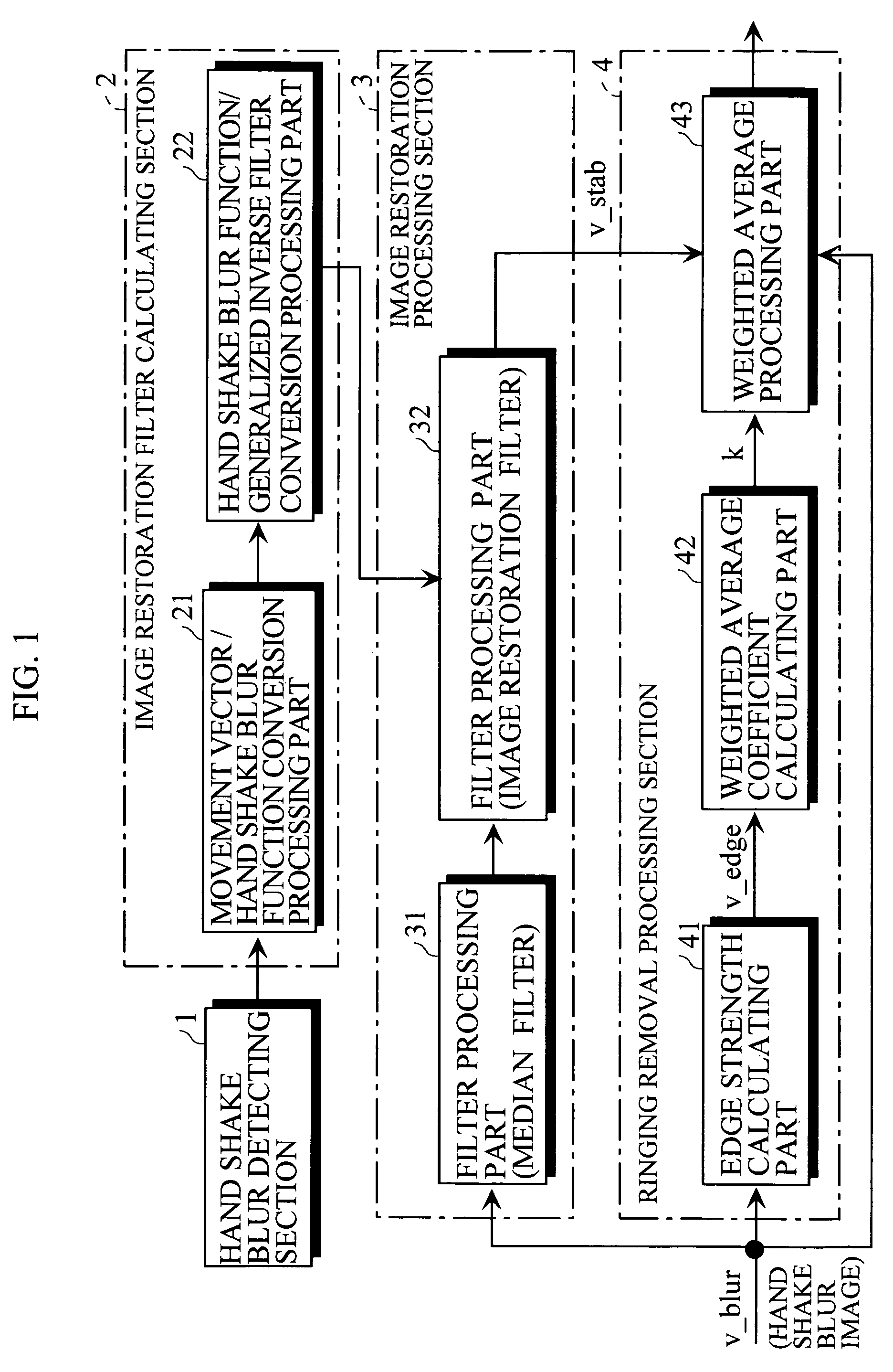
[0040]FIG. 1 shows the configuration of the hand shake blur correction processing circuit arranged in the digital camera.

[0041]The hand shake blur correction processing circuit includes a hand shake blur detecting section 1, an image restoration filter calculating section 2, an image restoration processing section 3, and a ringing removal processing section 4.

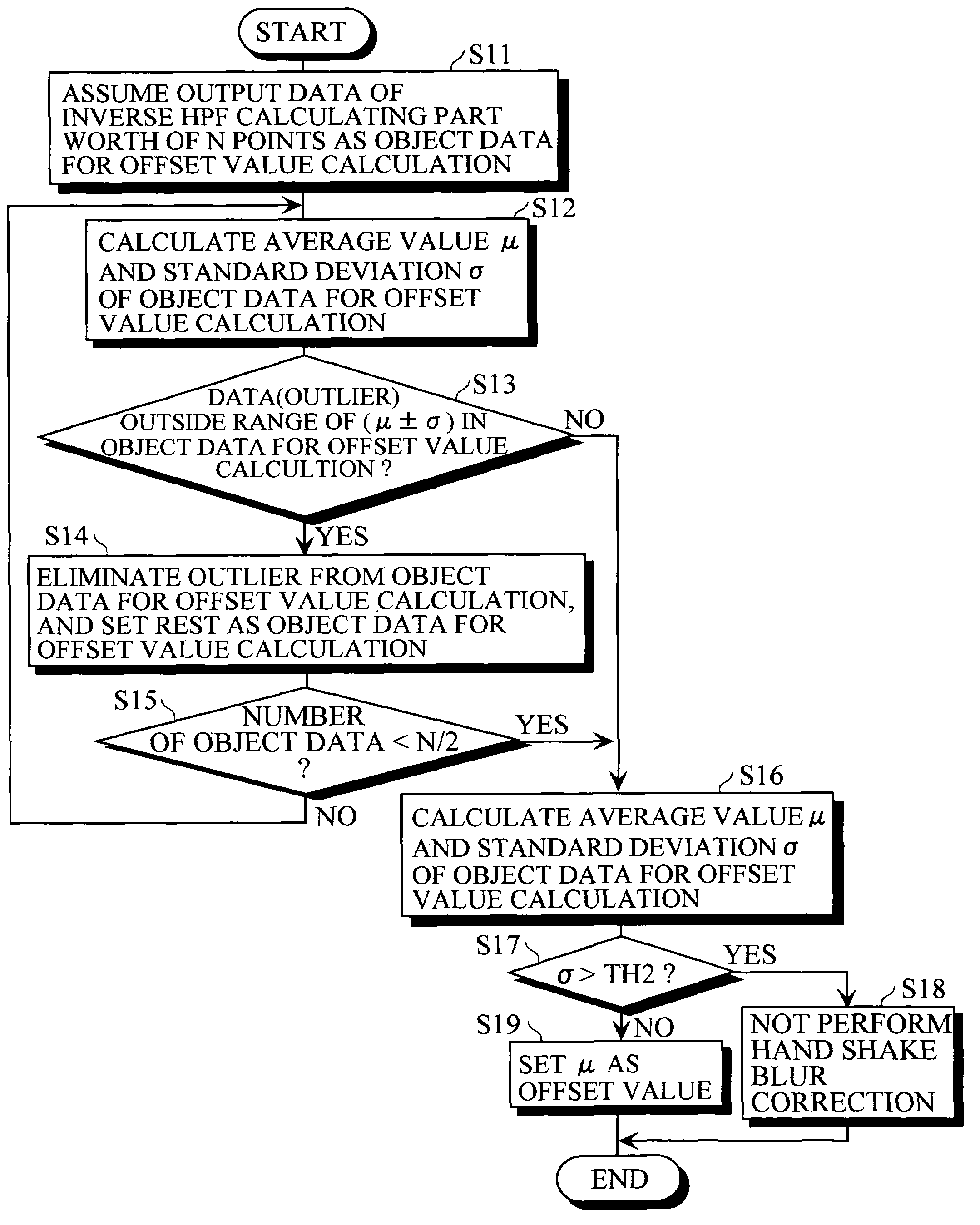
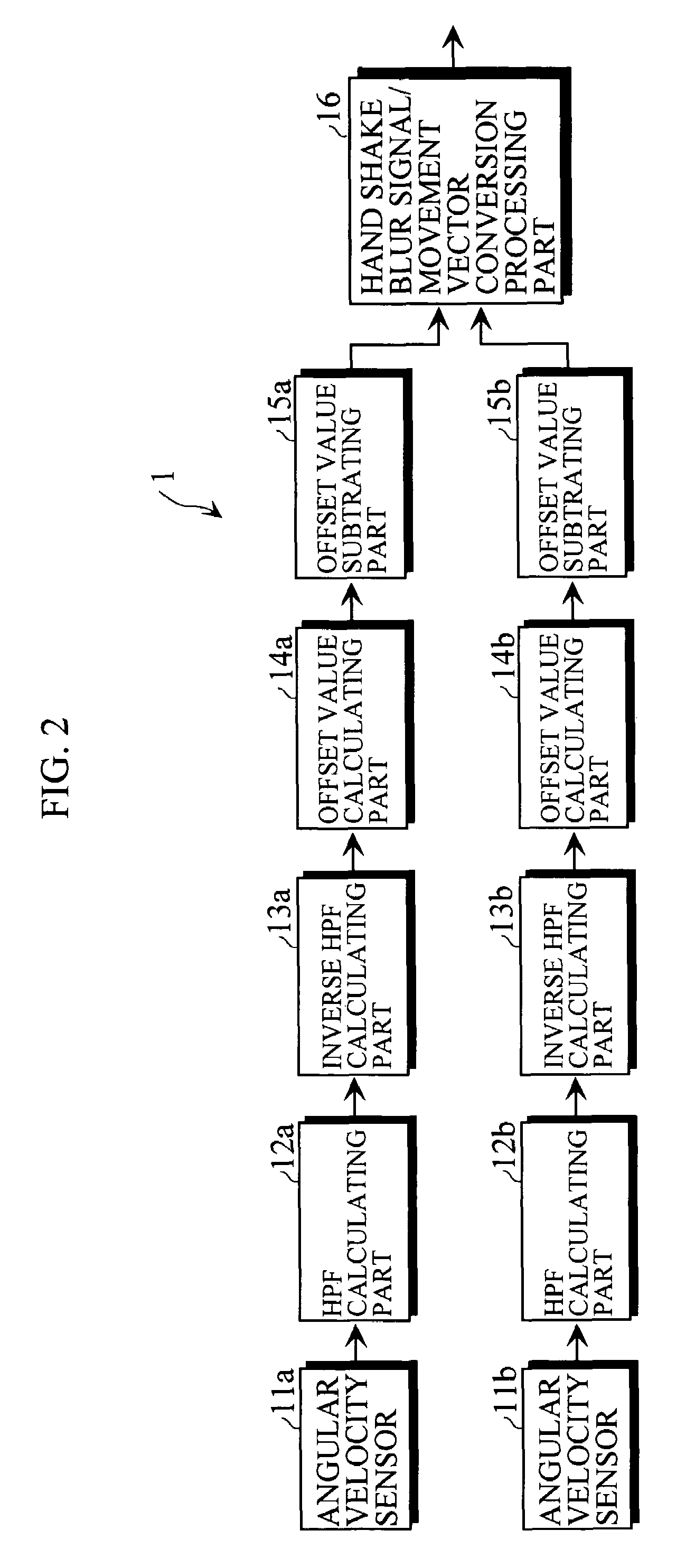
[0042]The hand shake blur detecting section 1 detects the hand shake blur of the digital camera. The image restoration filter calculating section 2 calculates the coefficient of the image restoration filter based on the hand shake blur signal detected by the hand shake blur detecting section 1. The image restoration processing section 3 performs image restoration process on the imaged image (hand shake blur image) based on the coefficient cal...


PUM


Abstract

A hand shake blur detecting apparatus for detecting hand shake blur of an imaging device based on an output signal of a hand shake blur sensor for detecting the hand shake blur of the imaging device is provided, the hand shake blur detecting apparatus including a high pass filter calculating part for removing low frequency component from the output signal of the hand shake blur sensor; an inverse high pass filter calculating part, having an inverse transfer function of a transfer function of the high pass filter calculating part, for filtering an output signal of the high pass filter calculating part; an offset value calculating part for calculating the offset value based on an output data of the inverse high pass filter calculating part; and an offset value subtracting part for subtracting the offset value calculated by the offset value calculating part from the output data of the inverse high pass filter calculating part.

Description

BACKGROUND OF THE INVENTION[0001]1. Field of the Invention[0002]The present invention relates to a hand shake blur detecting apparatus.[0003]2. Description of the Related Art[0004]A still image hand shake blur correction technique is a technique for reducing hand shake blur in photography (still image shooting), and is achieved by detecting the hand shake blur and stabilizing the image based on the detected result.[0005]A method of detecting the hand shake blur includes a method of using a hand shake blur sensor (angular velocity sensor), and an electronic method of detecting by analyzing the image. The method of stabilizing the image may be an optical method in which the lens and imaging sensors are stabilized, or an electronic method in which the blur caused by hand shake is removed through image processing.[0006]The completely electronic hand shake blur correction technique, that is, a technique of generating the image in which hand shake blur is removed by analyzing and processi...

Claims


Application Information

Patent Timeline
Patent Type & Authority Patents(United States)
IPC IPC(8): G03B17/00
CPCG03B5/00G03B17/00
Inventor HATANAKA, HARUOFUKUMOTO, SHINPEI
Owner XACTI CORP
Why Eureka
Try Eureka