Thermally initiated venting system and method of using same
a venting system and thermally initiated technology, applied in the direction of rocket engine plants, machine/engines, ammunition loading, etc., can solve the problems of munitions in which they are disposed to inadvertently explode prematurely, many are sensitive to heat and mechanical shock, unlikely material explosion or spontaneous burning
- Summary
- Abstract
- Description
- Claims
- Application Information
AI Technical Summary
Benefits of technology
Problems solved by technology
Method used
Image
Examples
first embodiment
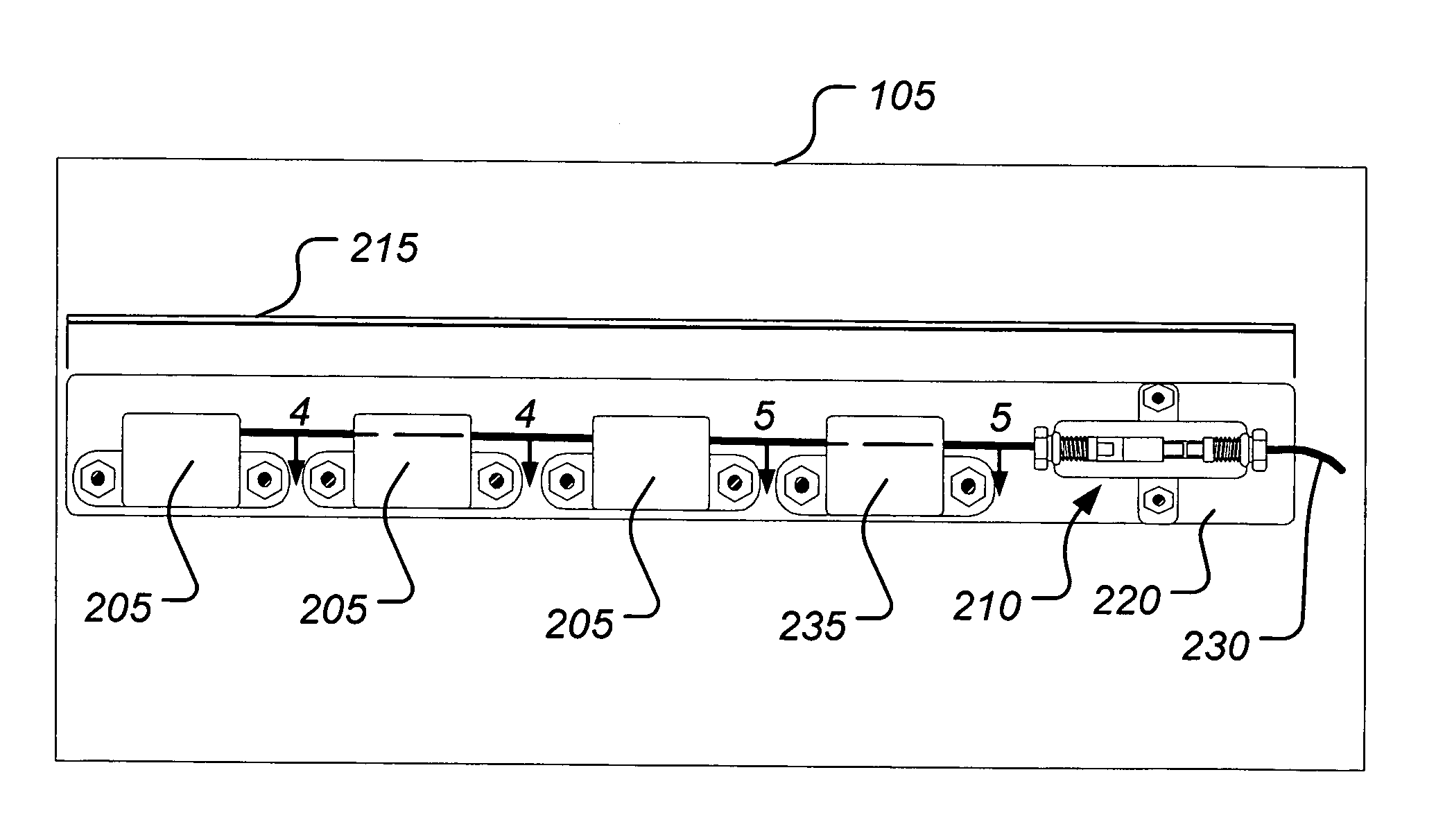
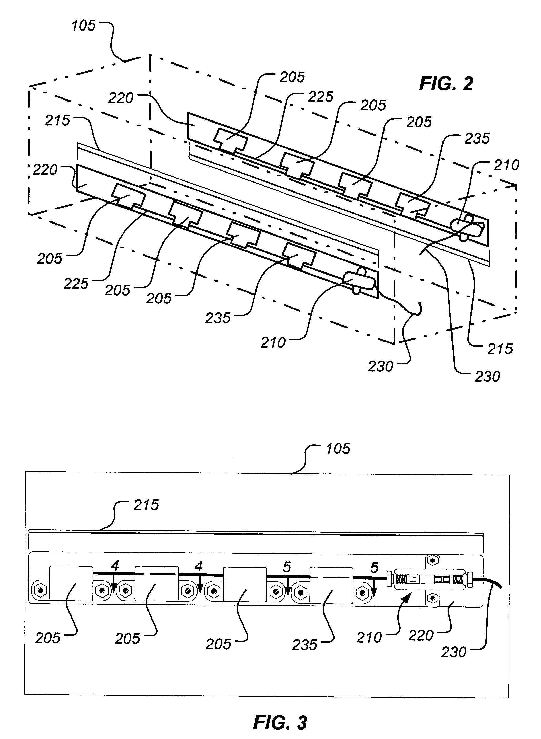
[0044]FIG. 2 provides a perspective view of the present invention in conjunction with a portion of the canister 105 proximate the propellant 115 (shown in FIG. 1). In the illustrated embodiment, one or more thermally-activated, deflagration initiation devices 205 and one or more deflagration-to-detonation transition manifolds 210 are attached to the canister 105 in two sets 215 via brackets 220. In alternative embodiments, however, the brackets 220 may be omitted in favor of attaching the initiation devices 205 and the transition manifolds 210 directly to the canister 105. In each of the sets 215, the initiation devices 205 are connected to the transition manifold 210 by a first transfer line 225 (e.g., a rapid deflagrating cord). The transition manifolds 210 are, in turn, connected by second transfer lines 230 (e.g., shielded mild detonating cords) to linear shaped charges (not shown in FIG. 2) disposed in the munition 100. As used herein, the term “linear shaped charge” includes l...
fourth embodiment
[0076]FIG. 21 provides a cross-sectional view of the present invention. In this embodiment, the thermally-activated initiation and detonation capabilities of each of the first three embodiments are incorporated into a single device. A venting device 2100, in the illustrated embodiment, comprises an initiation device 2105 coupled with a linear shaped charge 2110. The initiation device 2105 comprises a pyrotechnic train 2115, disposed within a housing 2117, that is adapted to initiate at a desired temperature or within a range of desired temperatures to detonate the linear shaped charge 2110.
[0077]In the illustrated embodiment, the pyrotechnic train 2115 comprises a heat-sensitive deflagration charge 2120 that is inactive below the predetermined propellant safety temperature and is activated above the propellant safety temperature or within a range of temperatures above the propellant safety temperature. Alternatively, the deflagration charge 2120 may be inactive below a predetermined...
fifth embodiment
[0080]FIG. 22 provides a cross-sectional view of the present invention. A venting device 2200, in the illustrated embodiment, comprises an initiation device 2203 coupled with a linear shaped charge 2210. The initiation device 2203 comprises a heat-sensitive propelling charge 2205 disposed within a cavity 2210 of a housing 2215. The material comprising the propelling charge 2205 is chosen to be inactive below the predetermined propellant safety temperature and is activated above the propellant safety temperature or within a range of temperatures above the propellant safety temperature. Alternatively, the propelling charge 2205 may be inactive below a predetermined minimum munition exhaust temperature and is activated above the minimum munition exhaust temperature or within a range of temperatures above the minimum munition exhaust temperature. In various embodiments, the propelling charge 2205 may comprise materials such as Cs2B12H12 / BKNO3, lead azide, hexanitrostilbene (HNS), and am...
PUM
 Abstract
Description
Claims
Application Information
 - R&D
- Intellectual Property
- Life Sciences
- Materials
- Tech Scout
- Unparalleled Data Quality
- Higher Quality Content
- 60% Fewer Hallucinations
Browse by: Latest US Patents, China's latest patents, Technical Efficacy Thesaurus, Application Domain, Technology Topic, Popular Technical Reports.
© 2025 PatSnap. All rights reserved.Legal|Privacy policy|Modern Slavery Act Transparency Statement|Sitemap|About US| Contact US: help@patsnap.com


