Quick-connect end fitting

a technology of end fittings and fast connections, applied in the direction of fastening/insulating connecting parts, electrical equipment, electric connection structural associations, etc., can solve the problem that mounting the clip inside the body sometimes gives rise to difficulties

Inactive Publication Date: 2009-05-12
ESTAB CAILLAU SARL
View PDF16 Cites 31 Cited by
  • Summary
  • Abstract
  • Description
  • Claims
  • Application Information

AI Technical Summary

Benefits of technology

[0040]The free ends of the clip are thus protected against any mishandling

Problems solved by technology

Such couplings are entirely satisfactory, but mounting the

Method used


Image

  • Quick-connect end fitting
  • Quick-connect end fitting
  • Quick-connect end fitting

Examples


Embodiment Construction

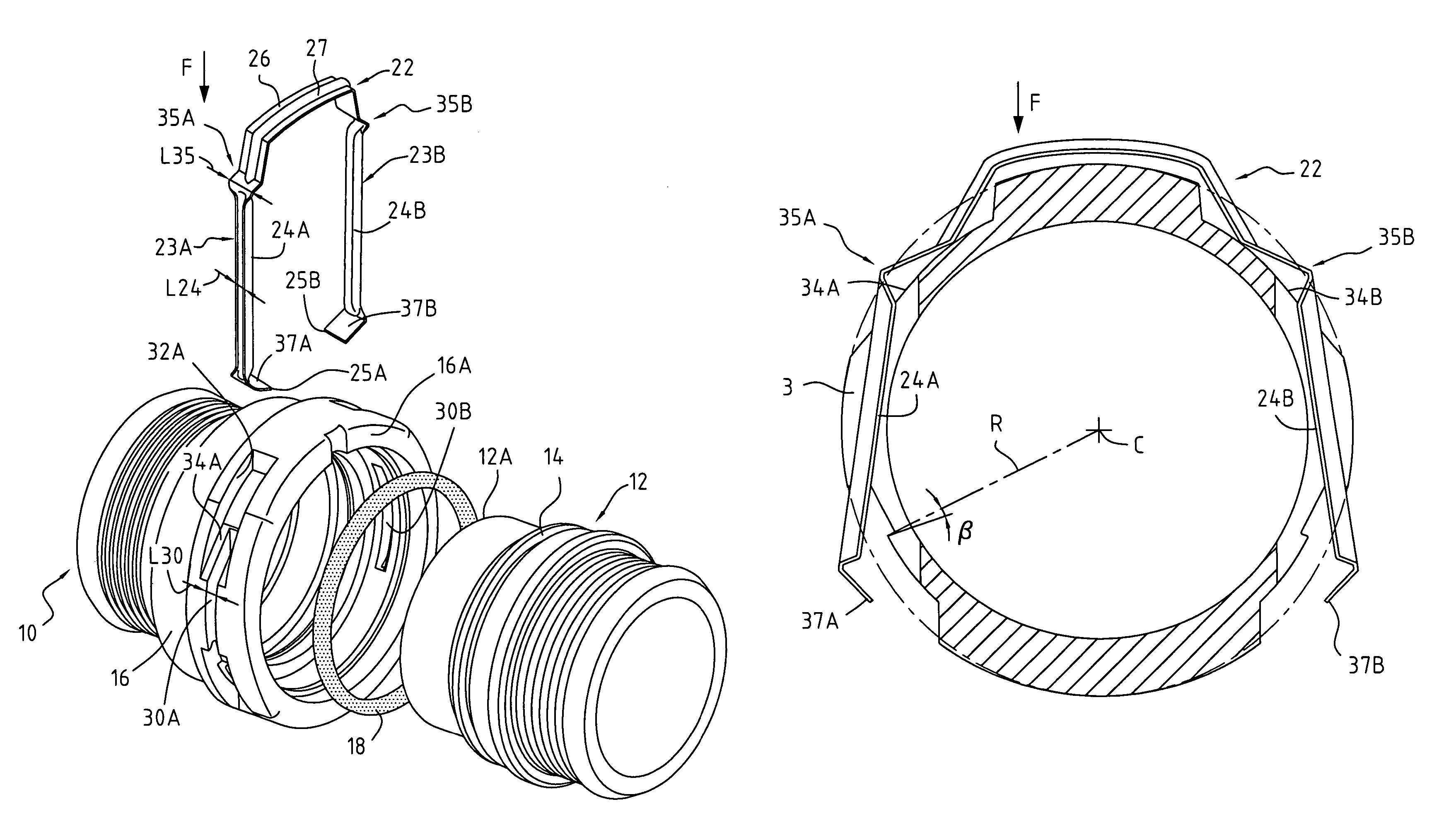
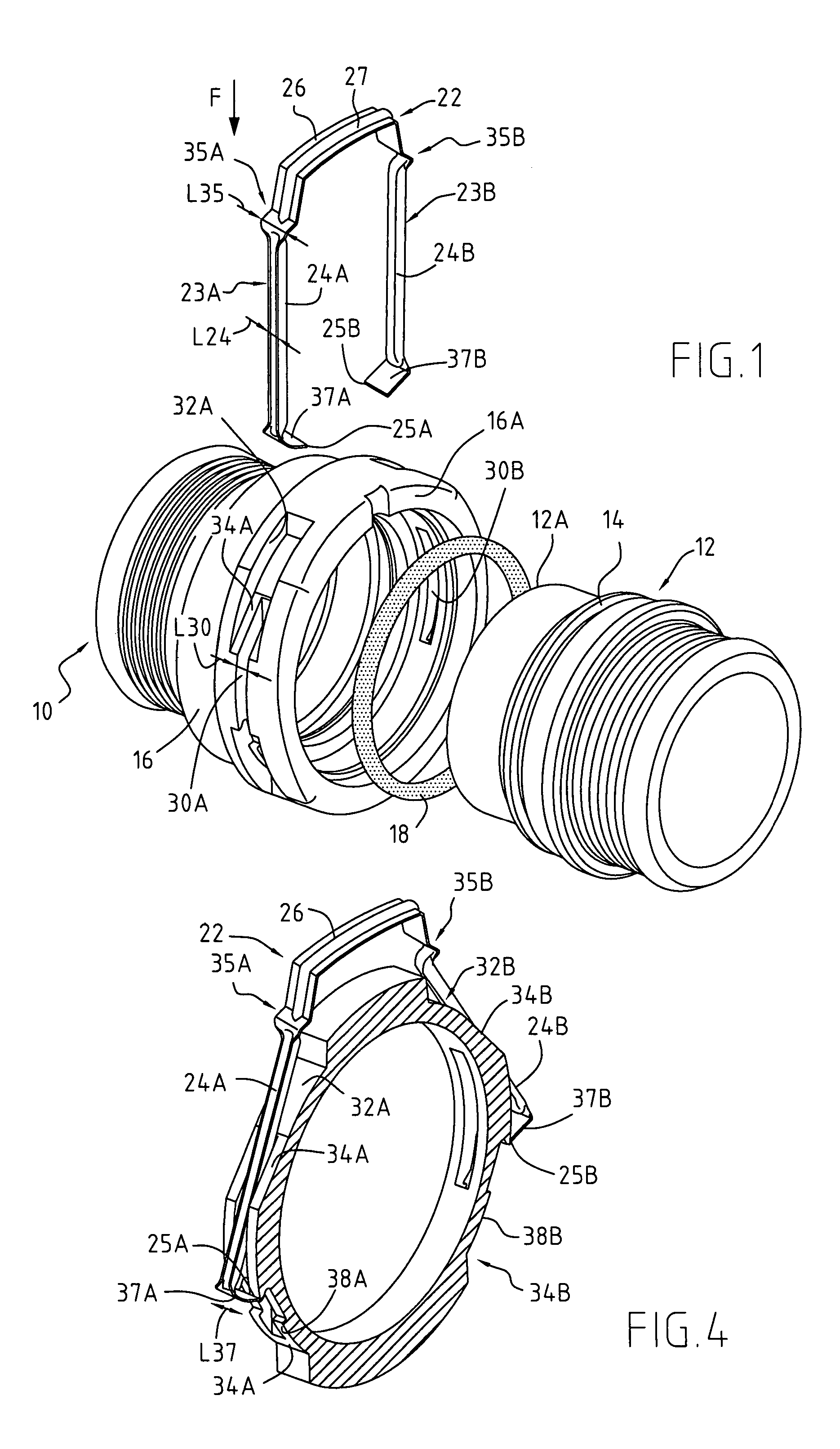
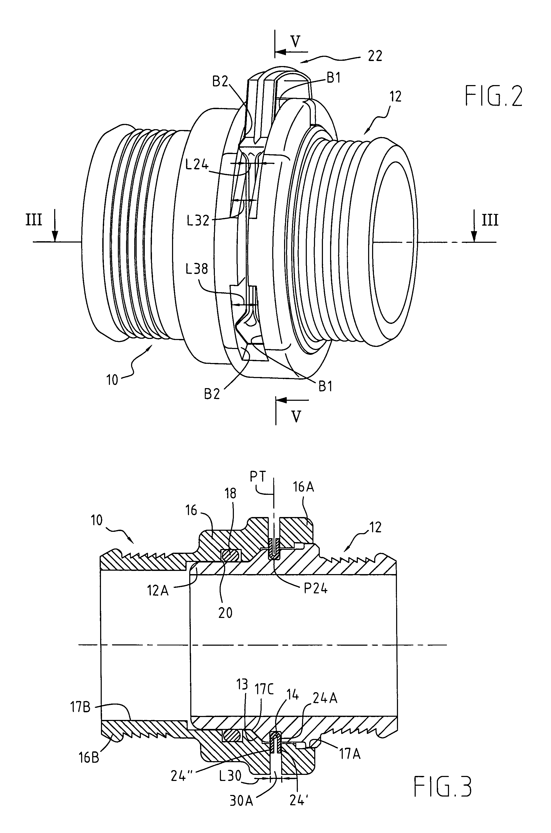
[0055]Firstly, FIGS. 1 to 3 are described below. They show the coupling 10 of the connection and the tube 12 onto which it is fitted. The tube presents a substantially radial catch surface 14 that is remote from its free end 12A.

[0056]The coupling 10 comprises a body 16 inside which the tube 12 can be fitted. In the fitted position shown in FIGS. 2 and 3, the connection between the tube and the coupling is leaktight. To this end, an O-ring sealing gasket 18 is disposed between the wall of the body of the coupling 16 and the wall of the tube 12. For example, a groove 20 is provided in the inside wall of the body of the coupling for the purpose of receiving said gasket 18, so that said gasket co-operates with an axial portion of the wall of the tube 12 when said tube is fitted into the coupling.

[0057]The coupling further comprises a locking clip 22 which, as can be seen more clearly in FIG. 2 is disposed over the wall of the body 16 of the coupling while being retained axially relativ...


PUM


Abstract

The coupling (10) comprises a body (16) suitable for being fitted onto a tube (12) in leaktight manner, and a locking clip (22) that is elastically deformable between a locking configuration in which at least one locking zone (24A, 24B) of the clip can catch on a catch surface (14) of the tube and an unlocking configuration. The clip (22) is disposed over the wall of the body (16), which wall is provided with at least one transverse slot (30A, 30B) through which the locking zone (24A, 24B) projects into the body when the clip is in the locking configuration, and with at least one setback (32A, 32B; 36A, 36B) provided at the end of the slot, a portion of the bottom of said setback forming an unlocking ramp (34A, 34B; 38A, 38B) on which an unlocking zone (35A, 35B; 37A, 37B) can slide in order to cause the clip to go from its locking configuration to its unlocking configuration. The width of the unlocking zone is greater than the width of the locking zone and than the width of the slot, but less than or equal to the width of the setback, said widths being measured axially.

Description

TECHNICAL FIELD[0001]The present invention relates to a quick-connect coupling suitable for being fitted axially onto a tube which presents a substantially radial catch surface remote from its free end, the coupling comprising a body suitable for co-operating with sealing means for establishing a leaktight connection with the tube, and a locking clip which is retained axially relative to the body and which presents at least one locking zone, the clip being such that, starting from a locking configuration in which it is suitable for co-operating with the catch surface of the tube in order to retain said tube, said clip is suitable for being deformed to take up an unlocking configuration.BACKGROUND ART[0002]Quick-connect couplings of this type are known, for example, from EP 0 911 565, and WO 02 / 08656.[0003]In such a coupling, the locking clip, also referred to as the “locking ring”, has an oblong shape and is disposed inside the body of the coupling, the wall of said coupling being p...

Claims


Application Information

Patent Timeline
IPC IPC(8): F16L37/00F16L37/084F16L37/14
CPCF16L37/088F16L37/144F16L37/0885F16L37/084F16L37/14
Inventor RIGOLLET, NICOLASPREVOT, FABRICEROINTRU, TONY
Owner ESTAB CAILLAU SARL
Why Eureka
Try Eureka