Sealed electrical terminal

a technology of electrical terminals and seals, applied in the direction of coupling contact members, multi-conductor cable end pieces, coupling device connections, etc., can solve the problem that seals may not prevent fluid seepag

Inactive Publication Date: 2009-05-12
YAZAKI NORTH AMERICA
View PDF19 Cites 88 Cited by
  • Summary
  • Abstract
  • Description
  • Claims
  • Application Information

AI Technical Summary

Benefits of technology

[0009]A further object of the invention is to eliminate the need for a seal crimp process to apply the seal on the terminal.

Problems solved by technology

Therefore, the seal may fail to prevent fluid seepage into the stripped end of the wire at the bond.

Method used


Image

  • Sealed electrical terminal
  • Sealed electrical terminal
  • Sealed electrical terminal

Examples


Embodiment Construction

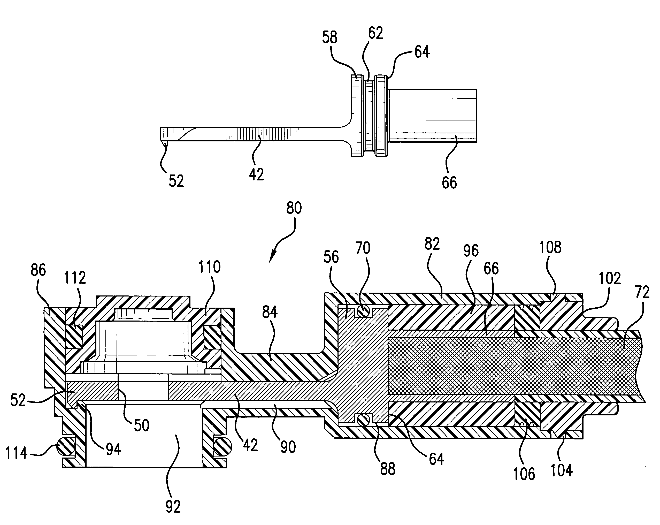
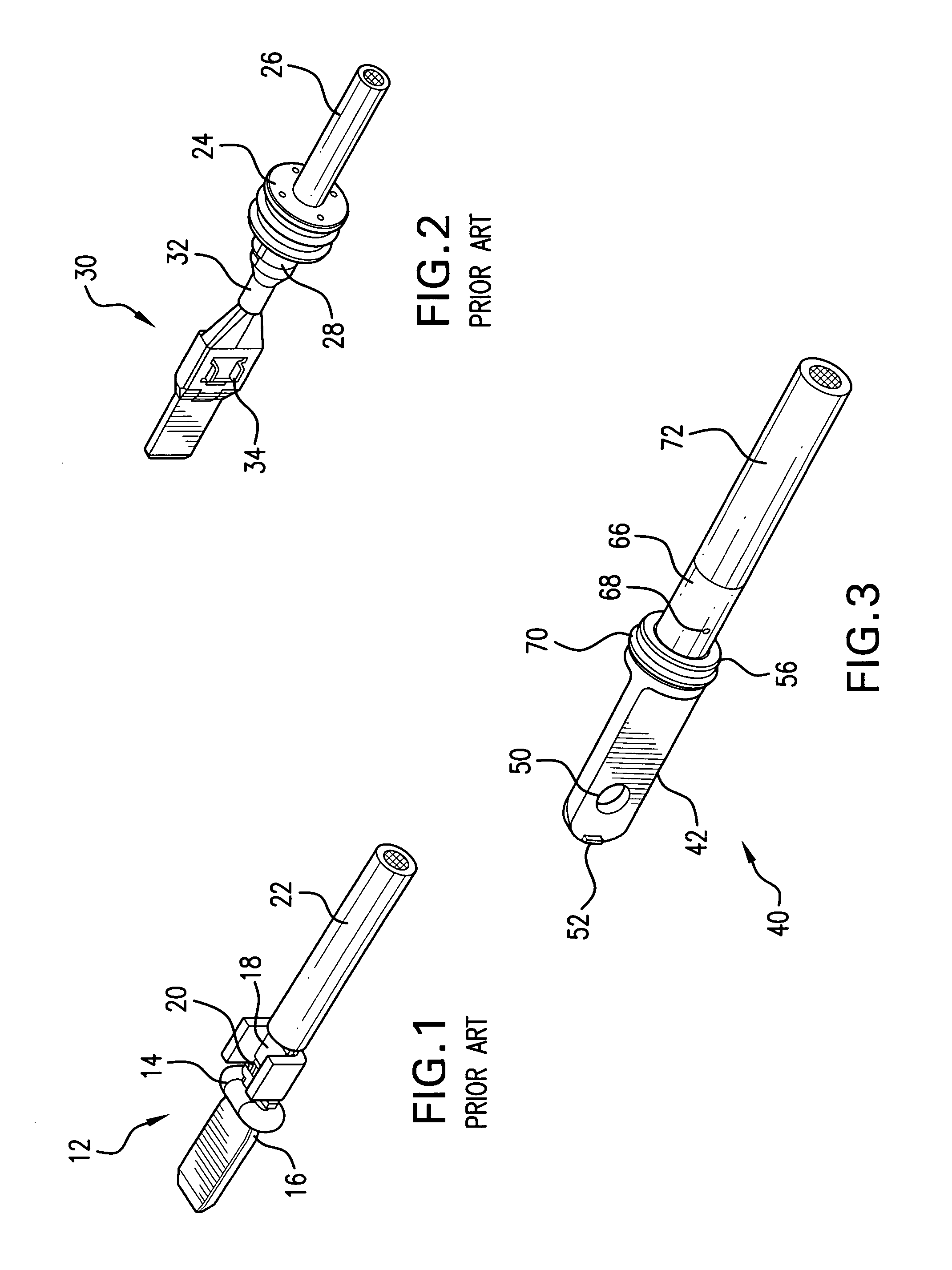
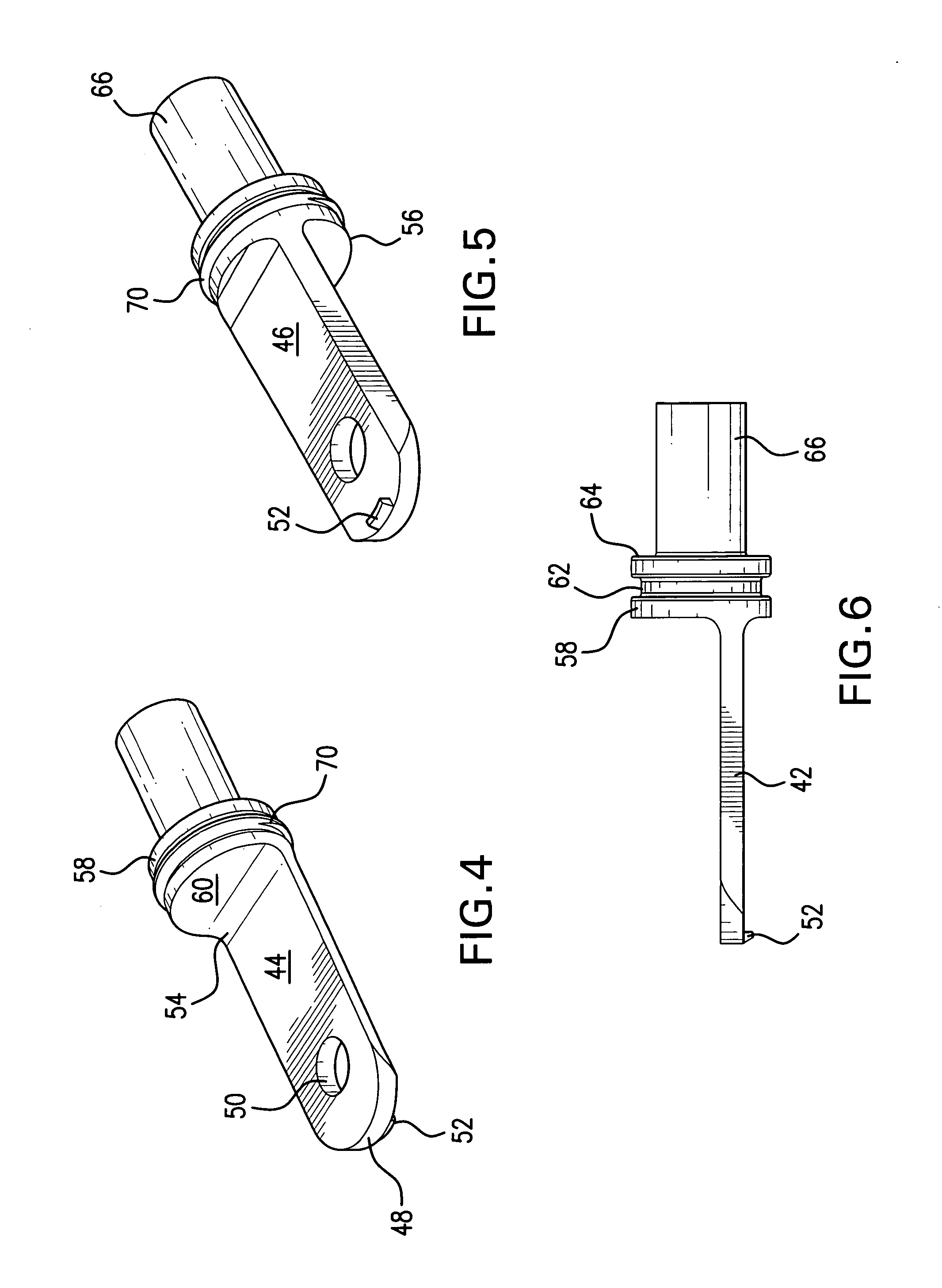
[0024]Referring now to FIGS. 3-6, an electrical terminal 40 according to the present invention has a substantially flat eyelet or contact section 42 for making electrical engagement with a mating element or component. As oriented in the FIGS. 4-6, the contact section 42 has an upper side 44 and an underside 46. The contact section 42 has a first, free end 48. An eyelet or aperture 50 adjacent the first end 48 extends through the contact section. A locking feature in the form of a hook-like projection 52 protrudes from the underside 46 of the contact section 42 at the first end 48. A second end 54 of the contact section 42 is integrally joined to an intermediate, cylindrical section 56. The cylindrical section 56 has an outer circumferential surface 58. The contact section 42 extends perpendicularly from a circular front stop or end face 60 of the cylindrical section 56 at an outer or lower region of the end face 60 as best illustrated in FIGS. 4-6. A groove 62 extends around the out...


PUM


Abstract

An electrical terminal is sealed for use in high voltage vehicle systems. The terminal has a cylindrical section positioned between a contact section for mating with another electrical contact or terminal and a crimp section for mechanically and electrically securing the terminal to an electrical wire. The cylindrical section is integral with both the contact section and the crimp section, and includes an outer surface with a circumferential groove. The groove receives and retains an o-ring seal for preventing contaminant seepage between the contact section and the crimp section when the contact section is inserted into a connector for mating with the other contact or terminal. The contact section may be either a substantially flat eyelet contact, a male contact or female contact.

Description

BACKGROUND OF THE INVENTION[0001]1. Field of the Invention[0002]The invention is directed in general to an electrical terminal for use in high voltage systems and more specifically to a terminal with a feature for optimally locating and securely holding a seal in position.[0003]2. Discussion of Related Art[0004]FIG. 1 illustrates a typical male blade terminal 12 with a wire seal 14. The seal 14 is positioned in a notch or cutout 16 in the terminal just to the front of a terminal bond portion 18. The bond portion attaches an insulation-stripped end 20 of a conductive wire 22 to the terminal. The seal 14 is generally not reliably held in position and can shift into an inefficient position when the terminal 12 is inserted into a terminal accommodating chamber in a connector housing. Therefore, the seal may fail to prevent fluid seepage into the stripped end of the wire at the bond. The fluid could travel along the wire 22 interior to damage a connected power module or connector.[0005]F...

Claims


Application Information

Patent Timeline
Patent Type & Authority Patents(United States)
IPC IPC(8): H01R13/40
CPCH01R4/183H01R11/12H01R13/521H01R13/5219Y10S439/921
Inventor TESFAY, SEMERE T.HASIJA, JOHN J.ADVEY, ALEXANDER J.
Owner YAZAKI NORTH AMERICA
Why Eureka
Try Eureka