
Quickly detached cooling fan mounting bracket for computer

a cooling fan and mounting bracket technology, applied in the direction of cooling/ventilation/heating modification, electrical apparatus, electrical components, etc., can solve the problems of difficult for consumers to reach the electrical components located at the bottom of the desktop computer's interior, inconvenient for consumers to repair or upgrade their desktop computers, and the cpu and the chipset generate more heat than other problems, to achieve the effect of quick removal and rapid replacement of electrical components

Inactive Publication Date: 2009-05-12
SHUTTLE
View PDF24 Cites 12 Cited by
  • Summary
  • Abstract
  • Description
  • Claims
  • Application Information

AI Technical Summary

Benefits of technology

"The present invention provides a cooling fan mounting bracket for a computer that allows for quick and easy removal of the cooling fan without detaching any other peripheral devices. This makes it easier to replace electrical components. The bracket includes a pivot axis that allows the cooling fan to rotate and be secured in place on the computer chassis. The bracket can be easily disconnected and assembled for installation. The bracket can also include small size hinges for easy maintenance and installation. Overall, the invention simplifies the process of installing and replacing computer components."

Problems solved by technology

But because of these added elements, the CPU and the chipset generate more heat than ever.
It is even harder for a consumer to reach electrical components located at the bottom of the desktop computer's interior.
The conventional art makes it inconvenient for the consumer to repair or upgrade his desktop computer.
In addition to the standard desktop computer devices mentioned above, a large electrical device installed within the desktop computer is the thermal dissipation assembly, which also takes up considerable space within the desktop computer.
This method does not make it easy for a consumer to remove the cooling fan.
Further, because the thermal dissipation device is assembled before it is installed inside the computer's chassis, it is difficult to remove the cooling fan alone.

Method used


Image

  • Quickly detached cooling fan mounting bracket for computer
  • Quickly detached cooling fan mounting bracket for computer
  • Quickly detached cooling fan mounting bracket for computer

Examples


Embodiment Construction

[0021]Reference will now be made in detail to the preferred embodiments of the present invention, examples of which are illustrated in the accompanying drawings. Wherever possible, the same reference numbers are used in the drawings and the description to refer to the same or like parts.

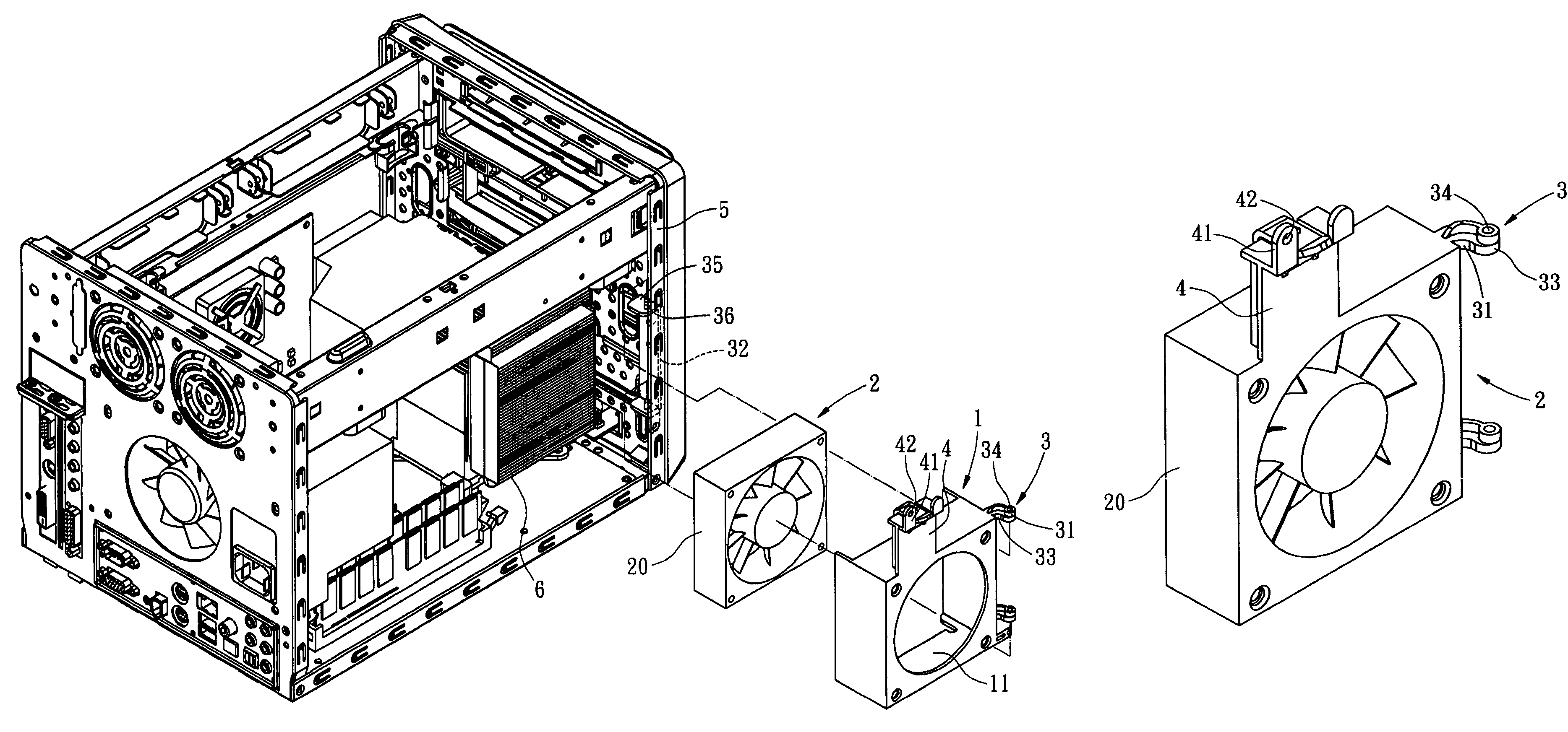
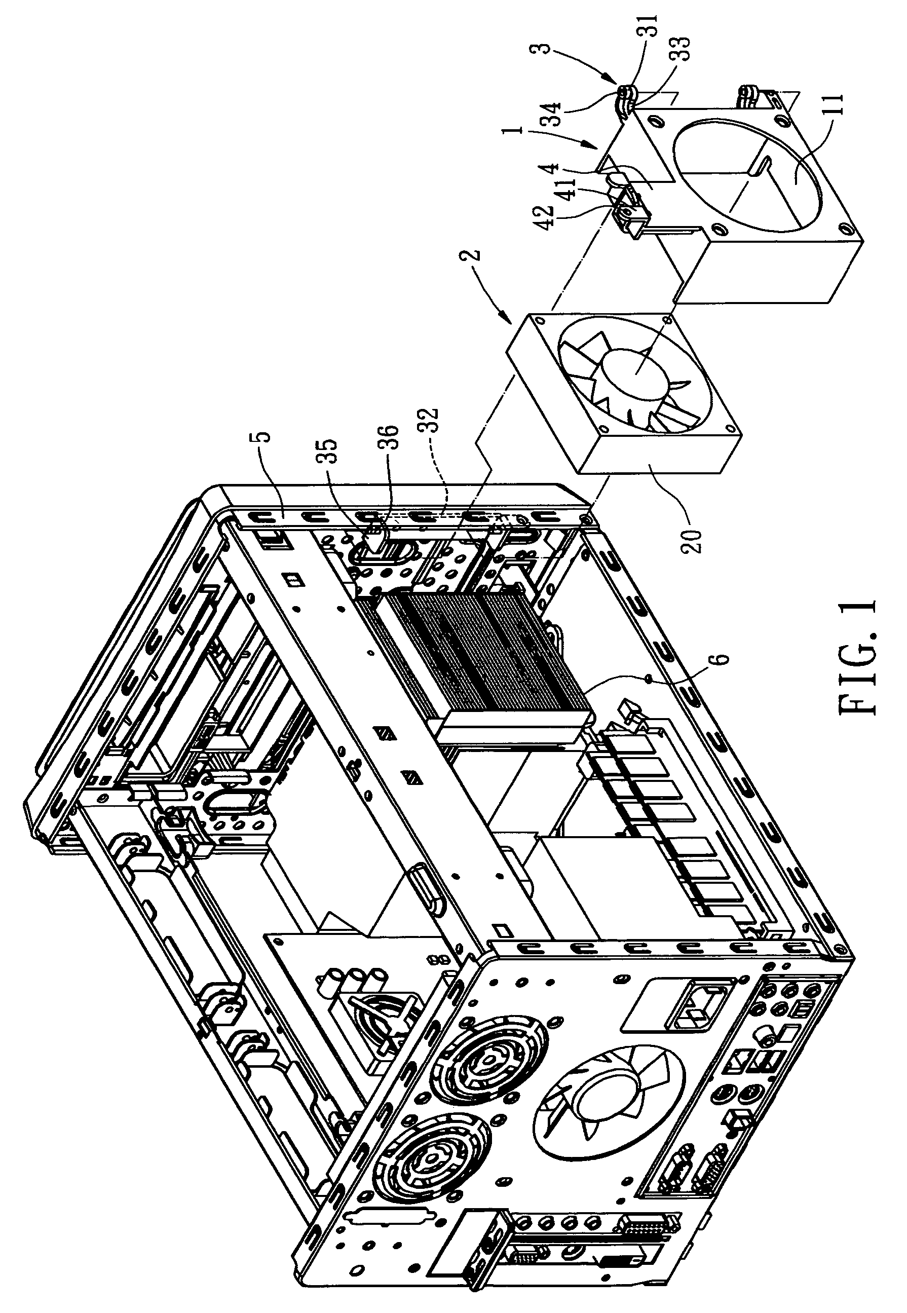
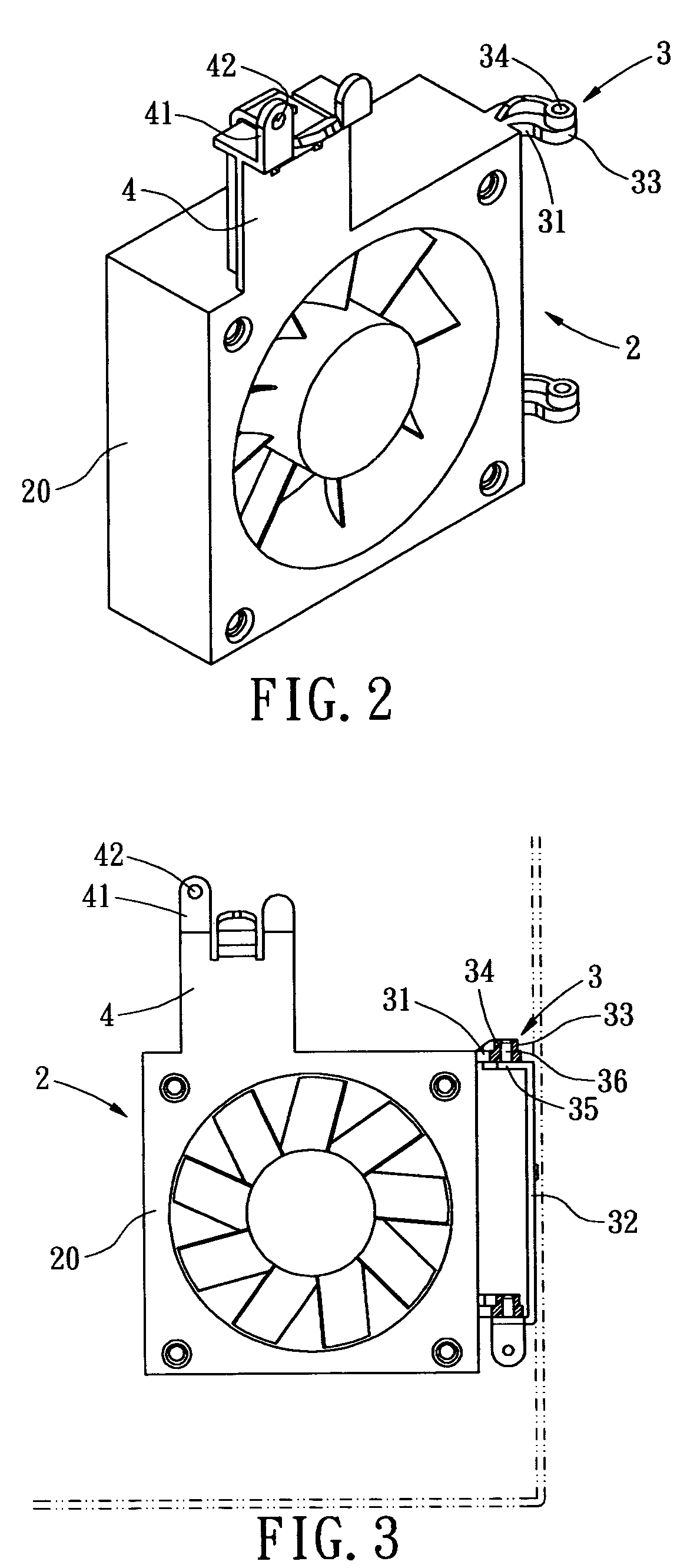
[0022]Referring to FIG. 1, one embodiment of a quickly detached cooling fan mounting bracket for a computer in accordance with the present invention is shown. The cooling fan mounting bracket includes a cooling fan receptive mount 1; a cooling fan 2; a connecting member 3, which allows the cooling fan receptive mount 1 to be movably installed on the computer chassis 5; and a orienting member 4, which provides the cooling fan receptive mount 1 and the cooling fan 2 with a means for orientation and installment.

[0023]The cooling fan receptive mount 1 provides the cooling fan 2 with a moveable structure that the cooling fan 2 can be installed into. There is no special requirement regarding the style and ...


PUM


Abstract

A quickly detached cooling fan mounting bracket for a computer, by which a cooling fan can be quickly removed away from a computer chassis without detaching any other peripheral devices, whereby a large enough computer inner space is exposed in order to facilitate rapid replacement of electrical components. The cooling fan mounting bracket includes a cooling fan receptive mount; a cooling fan; a connecting member, which allows the cooling fan receptive mount to be movably installed on the computer chassis; and a orienting member, which secures the cooling fan receptive mount and the cooling fan onto the computer chassis, and prevents the cooling fan from vibration during the normal operation. Compared with the conventional art, the present invention is easier to remove the cooling fan away from the chassis, thereby, facilitates rapid replacement or maintenance of the computer components.

Description

BACKGROUND OF THE INVENTION[0001]The present invention relates in general to a cooling fan mount set by which a cooling fan is secured inside a electrical apparatus, and more particularly, to a quickly detached cooling fan mounting bracket for a computer, by which a cooling fan can be quickly removed away from a computer chassis without detaching any other peripheral devices, whereby a spacious computer inner space is exposed in order to facilitate rapid replacement of electrical components.[0002]The design of electrical instruments today, and especially the desktop computer, focuses not only on processing speed and multifunction capability, but also on attaining a compact size and attractive appearance. In spite of its decreasing size, the desktop computer is even more powerful and has even more functions than ever is. The desktop computer can have this added power and functionality because there are more powerful electrical components installed thereinside.[0003]In order to enhanc...

Claims


Application Information

Patent Timeline
Patent Type & Authority Patents(United States)
IPC IPC(8): H05K5/00
CPCH05K7/20172
Inventor CHEN, SHIH-TSUNG
Owner SHUTTLE
Learn More