Battery fuel gauge circuit

a fuel gauge and battery technology, applied in the field of rechargeable batteries, can solve the problems of increasing the cost and complexity of portable electronic appliances, complex system of battery packs, and costly manufacturing

Active Publication Date: 2009-05-12
O2 MICRO INT LTD
View PDF8 Cites 16 Cited by
  • Summary
  • Abstract
  • Description
  • Claims
  • Application Information

AI Technical Summary

Problems solved by technology

Simply speaking, the battery pack is a complex system of components working in harmony to safely deliver power to any type of the above-mentioned portable electronic appliances.
In order to determine the capacity of the battery pack, some prior art solutions utilize numerous components and different algorithms, and are costly to be manufactured although higher accuracy of the prediction of the battery pack can be achieved by these solutions.
These solutions usually rely on software and analog-to-digital converters (ADCs) that increase the cost and complexity of the portable electronic appliances.
As a result, these solutions will be not worth for some small and low cost applications.
The usual drawback of these solutions is that they have low accuracy, low efficiency or bad performance.
With these solutions, it is difficult to accurately predict the remaining capacity of the rechargeable batteries.

Method used


Image

  • Battery fuel gauge circuit
  • Battery fuel gauge circuit
  • Battery fuel gauge circuit

Examples


Embodiment Construction

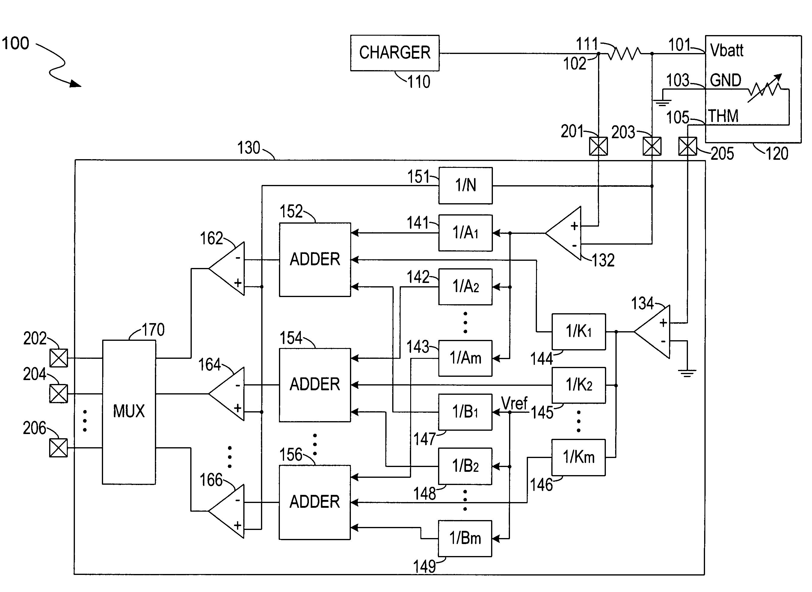
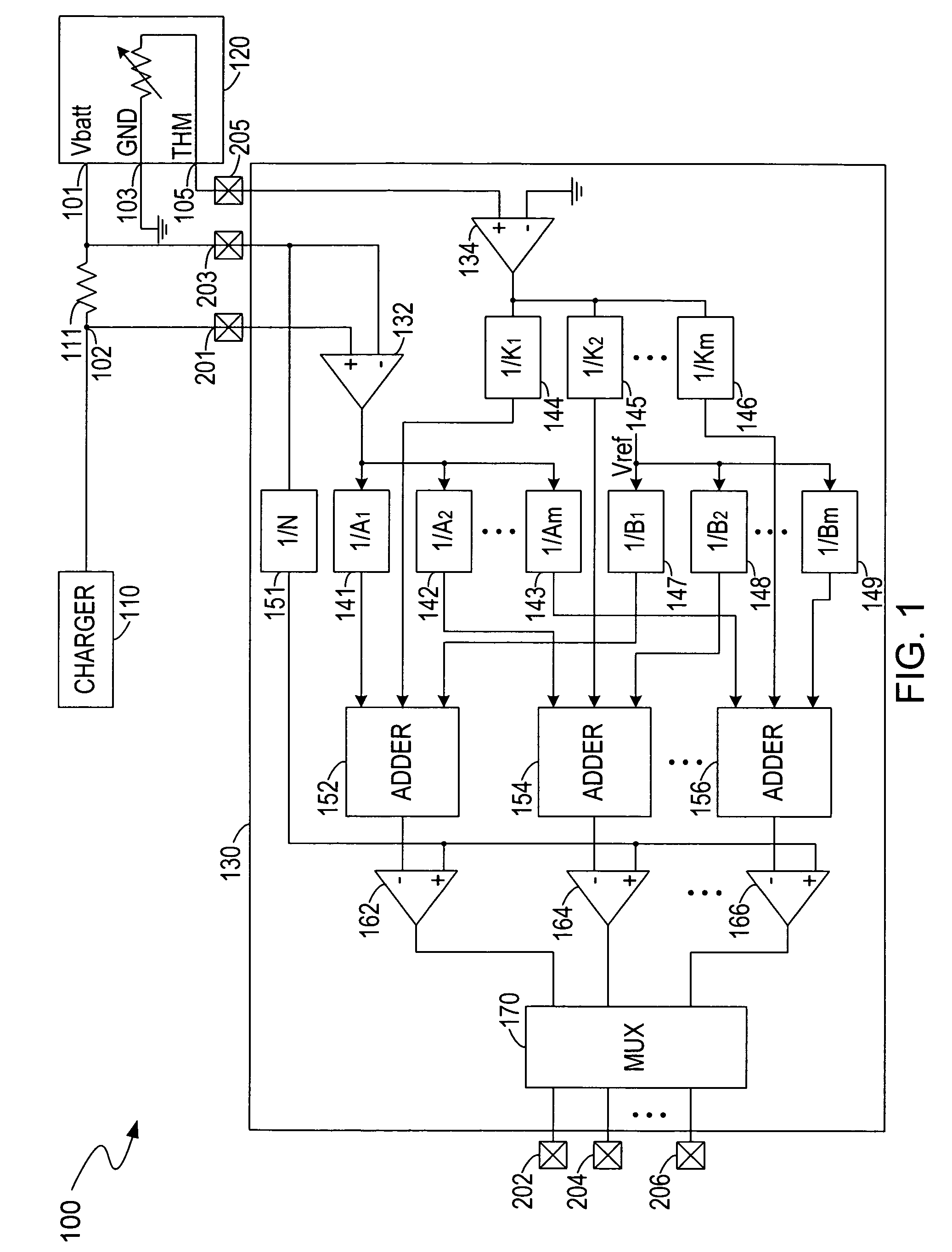
[0019]Briefly described, the invention provides a correction circuit to a battery fuel gauge circuit, so that the battery fuel gauge circuit can detect the amount of energy (the remaining charges) stored in a rechargeable battery cell or a rechargeable battery pack without adding the complexity or lowering the accuracy of the battery fuel gauge circuit. FIG. 1 illustrates a simplified block diagram of an exemplary battery fuel gauge device 100. The battery fuel gauge device 100 includes a charger 110, a rechargeable battery pack 120, and a battery fuel gauge circuit 130. The battery fuel gauge device 100 can generate an appropriate operating voltage to source an external application system at node 102 based upon the remaining energy in the battery pack 120. In this embodiment, the battery fuel gauge circuit 130 is utilized to detect the amount of the remaining energy in the battery pack 120. Furthermore, the battery fuel gauge circuit 130 can implement discharge current correction a...


PUM


Abstract

The present invention is a battery fuel gauge circuit for measuring the capacity of a battery pack. The battery fuel gauge circuit includes an amplifier circuit, a correction circuit, a plurality of comparators, and a multiplexer. The amplifier circuit can sense a discharge current flowing through a sense resistor and a variable temperature from the battery pack and generate a first and a second voltage signals, which are corrected by the correction circuit and compared with a reference voltage by the plurality of comparators. After correction and comparison, the multiplexer can transmit the compared signals to an external indicating circuit that controls the display of the capacity of the battery pack.

Description

RELATED APPLICATION[0001]This application claims the benefit of U.S. provisional application, titled Integrated Parametric Battery Fuel Gauge Meter, Ser. No. 60 / 732,560, filed on Nov. 2, 2005, the specification of which is incorporated herein in its entirety by this reference.BACKGROUND OF THE INVENTION[0002]1. Field of the Invention[0003]The present invention relates to rechargeable batteries and in particular to a battery fuel gauge circuit for detecting the capacity of the rechargeable batteries.[0004]2. Description of the Related Art[0005]Currently, portable electronic appliances are becoming more and more common in today's society as the capabilities and uses of such appliances continue to expand. The portable electronic appliances may include, by way of example, laptop computers, cell phones, personal digital assistants (PDAs), pagers, camcorders, digital cameras and other devices. Many portable electronic appliances are powered by rechargeable batteries, i.e., secondary batte...

Claims


Application Information

Patent Timeline
Patent Type & Authority Patents(United States)
IPC IPC(8): H02J7/16
CPCG01R31/3624G01R31/3648G01R19/16542G01R31/3675G01R31/3842G01R31/374
Inventor MAIREANU, STEFAN
Owner O2 MICRO INT LTD
Why Eureka
Try Eureka