Fiber optic link protection apparatus

a fiber optic link and protection device technology, applied in the field of optical communication networks, can solve problems such as reducing the performance of the network

Inactive Publication Date: 2009-05-12
LIGHTECH FIBEROPTICS
View PDF17 Cites 18 Cited by
  • Summary
  • Abstract
  • Description
  • Claims
  • Application Information

AI Technical Summary

Benefits of technology

The technical effect of this patent is to protect the connection between two points in a fiber-optic communications network from damage or interference that could disrupt the signal transfer.

Problems solved by technology

This patent discusses different techniques for protecting optical communication networks from failures and ensuring continued operation even in the event of a failure. The technical problem addressed is how to quickly detect and isolate the failed component(s) while minimizing loss of data and improving overall efficiency of the network.

Method used


Image

  • Fiber optic link protection apparatus
  • Fiber optic link protection apparatus
  • Fiber optic link protection apparatus

Examples


first embodiment

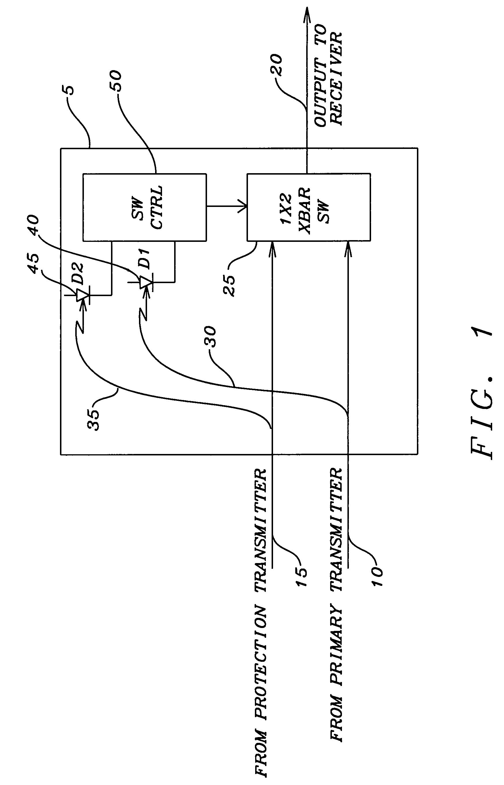
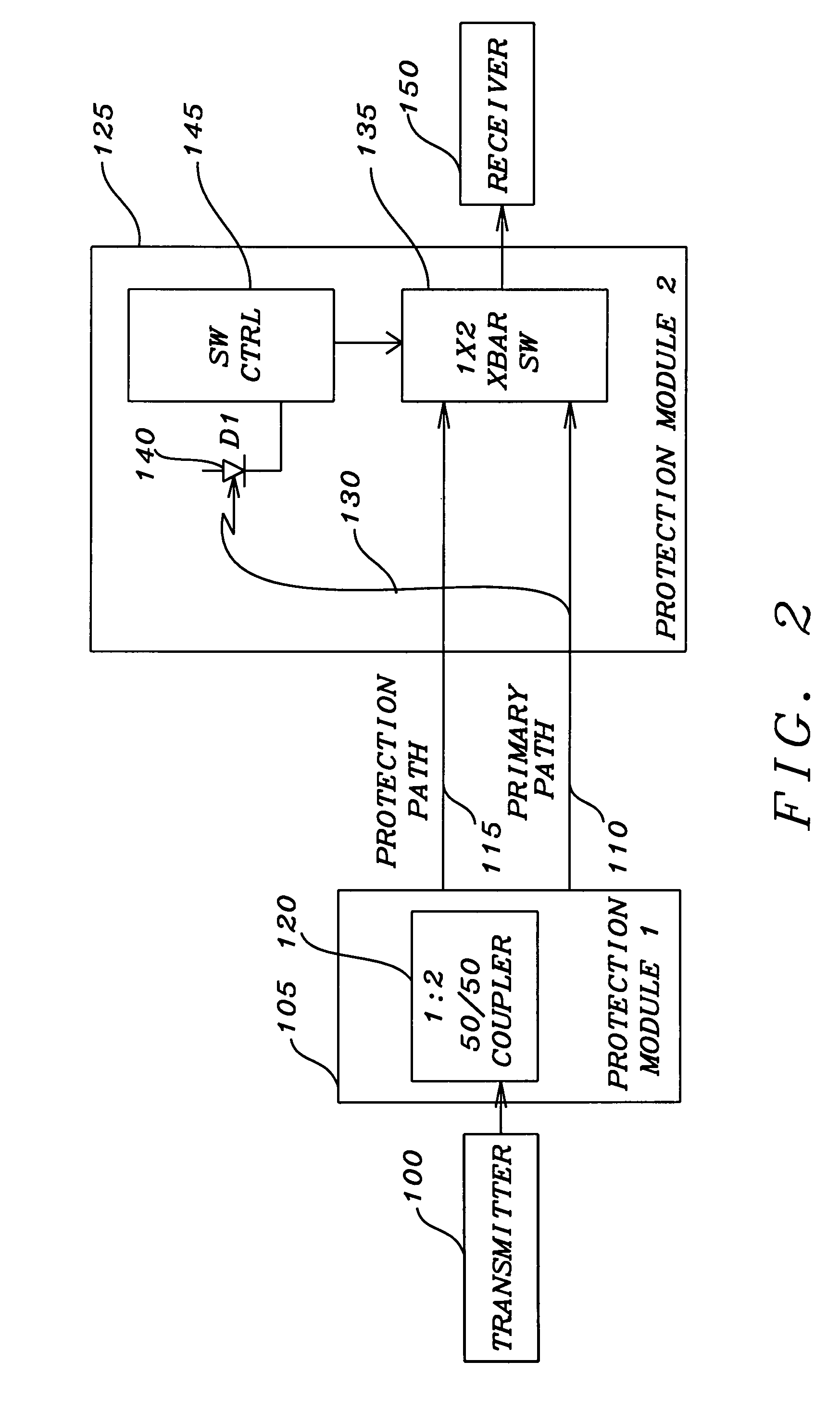
[0036]an optical link between two nodes of a network is shown in FIG. 2. A first node has a transmitter 100 that is to convey the optical signal from the first node. The output of the transmitter 100 is connected to a first protection module 105. The first protection module 105 has an optical coupler that divides the optical signal into equal portions that are to be conveyed on the primary optical transmission path 110 and the protection optical transmission path 115. The primary optical transmission path 110 and the protection optical transmission path 115 are connected to the second protection module 125, which in turn is connected to the receiver 150 of a second node. The primary optical transmission path 110 and the protection optical transmission path 115 are connected to the two input / one output crossbar switch 135 of the second protection module 125. The output of the crossbar switch 135 is connected to the receiver 150 of the second node. The optical signal present on the pr...

second embodiment

[0049]FIG. 4b illustrates this structure employing a return transmitter and wave domain multiplexer. The fundamental structure of the fiber optic link of FIG. 4b is essentially identical to that of FIG. 4a, except the wave domain multiplexer 340 is now connected to the primary optical transmission path 315 through the tap 345. The transmitter 309 transmits a constant optical signal that does not need to contain any message, but may be modulated for power conservation purposes. The tap 325 is now in the primary optical transmission path 315 rather than the secondary optical transmission path 320 as in FIG. 4a. The constant optical sense signal impinges on the photodiode 312 to create a sense current that is transferred to the switch control circuit 313. If the constant optical sense signal is functioning indicating that there is no fault in the primary optical transmission path 315, the switch control circuit 313 generates a control signal that is communicated to the crossbar switch ...


PUM


Abstract

A fiber optic protection apparatus includes a first optical switch, a first fault detection device, and first switch control device. The first optical switch is placed at the reception node of an optical link and has a primary input port connected to a primary optical transmission path. A secondary input port is connected to one secondary optical transmission path. The first fault detection device is in communication with the primary optical transmission path to identify a fault within the primary optical transmission path and to generate a fault signal indicating type or location of the fault. The fault signal is transferred to the first switch control device that is in communication with the optical switch. This causes the optical switch to connect one of the secondary optical transmission paths to the reception node when the fault signal indicates that the primary optical transmission path has a fault.

Description


Claims


Application Information

Patent Timeline
Owner LIGHTECH FIBEROPTICS
Why Eureka
Try Eureka