Engine control apparatus, control method and control system

a control apparatus and control system technology, applied in the direction of engine starters, hybrid vehicles, instruments, etc., can solve the problems of not being able to charge lithium ion batteries at the same time, not being able to achieve the effect of improving gas mileage and not improving gas mileag

Inactive Publication Date: 2009-05-19
FUJITSU GENERAL LTD
View PDF67 Cites 19 Cited by
  • Summary
  • Abstract
  • Description
  • Claims
  • Application Information

AI Technical Summary

Benefits of technology

[0011]It is therefore an object of the invention to provide an engine control apparatus, a control method and a control system for the twin-battery type economical running system which can restore the voltage of a second battery to a voltage at which an economical running can be permitted as soon as possible while preventing the voltage of a first battery as the main battery from voltage reduction in the event that the voltage of the second battery is reduced by reviewing the charging method of the second battery and the control method of a current limiter of a voltage regulator.
[0033]In the related art economical running system employing two batteries, if the voltage of the second battery is lower than the second predetermined value, the function of charging the second battery is not performed except the case of decreasing the speed of a vehicle so that the engine for economical running is not stopped. Therefore, in the related art economical running system employing two batteries, the gas mileage may not be improved. However, according to the present invention, even if a voltage of the second battery is lower than the second predetermined value, the function of charging the second battery is performed under the conditions other than the case of decreasing the speed of a vehicle. Therefore, the voltage of the second battery may be restored in an early stage so that the engine for economical running may be stopped and accordingly, the gas mileage may be improved.

Problems solved by technology

The lithium ion battery having the 12V output voltage is not suitable as auxiliary battery for mounting on the vehicle.
In the twin-battery type economical running system that is configured as has been described above, however, when the lithium ion battery is charged, since the limiter of the DC / DC converter is released only when the battery is charged while the vehicle is decelerated, current that charges the lithium ion battery is not much, leading to a problem that it takes much time to charge the lithium ion battery.
Due to this, when the vehicle comes to be idled in such a state that the voltage of the lithium ion battery is low, a long time is needed until an economical running is permitted which is enabled when the voltage of the lithium ion battery is high, leading to a problem that the number of times of permitting the economical running is reduced.

Method used


Image

  • Engine control apparatus, control method and control system
  • Engine control apparatus, control method and control system
  • Engine control apparatus, control method and control system

Examples


first embodiment

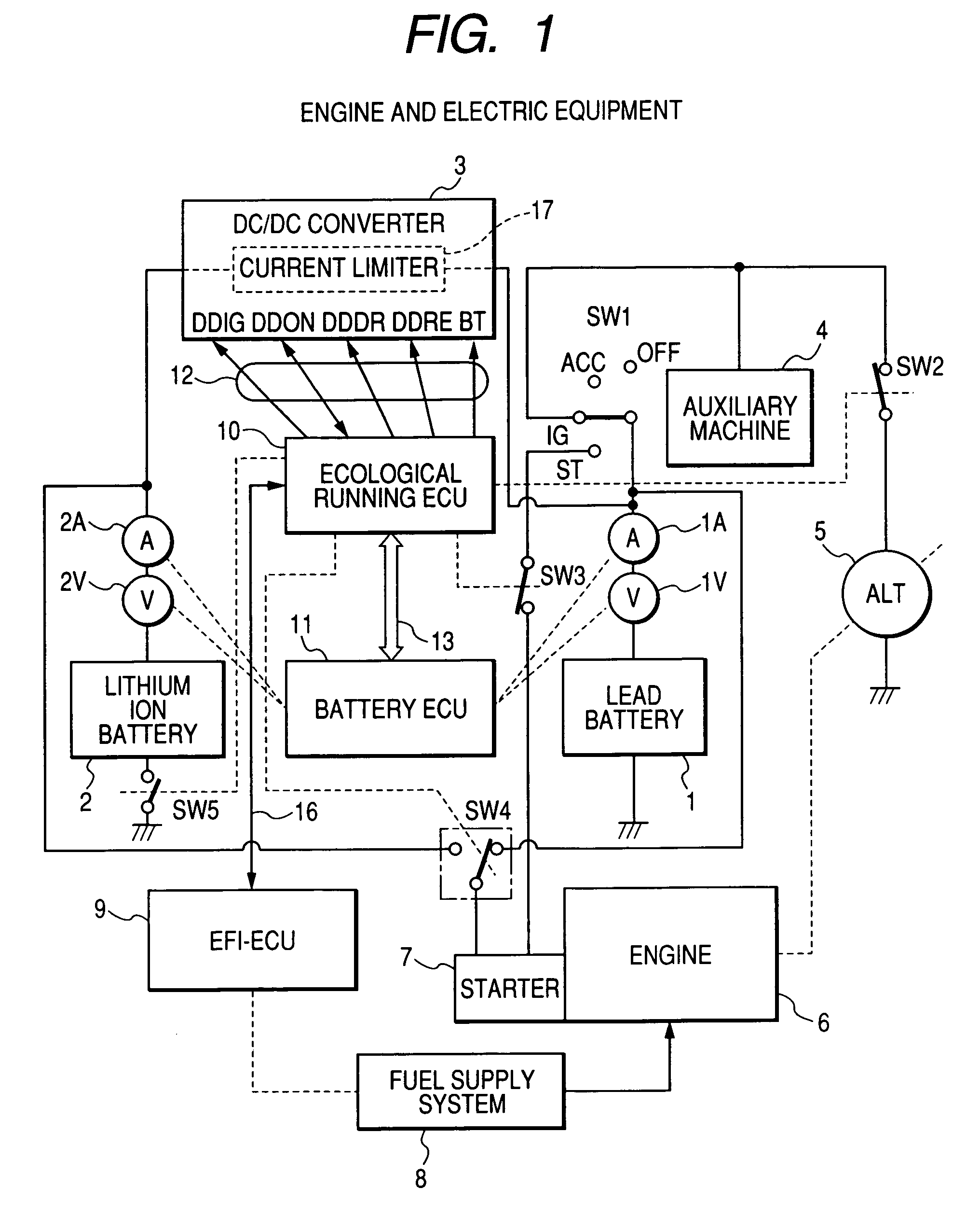
[0068]FIG. 3(a) is such as to show the invention and shows specifically a current limitation control by the DC / DC converter in the charge control on the lithium ion battery. In this embodiment, the current limit value of the current limiter incorporated in the DC / DC converter is changed according to a value of current which flows into the side of the lithium ion battery 2 while the lithium ion battery is charged, with the voltage value LiV of the lithium ion battery being equal to or smaller than V0 and the voltage value PbV of the lead battery 1 being equal to or larger than V1. In addition, FIG. 3(b) is a time chart which shows a transition of the current limit value of the DC / DC converter according to a control procedure shown in FIG. 3(a).

[0069]Note that in the embodiment shown in FIG. 3(a), an example will be described in which the current limit value of the current limiter incorporated in the DC / DC converter is released in the event that the value of current which flows into t...

second embodiment

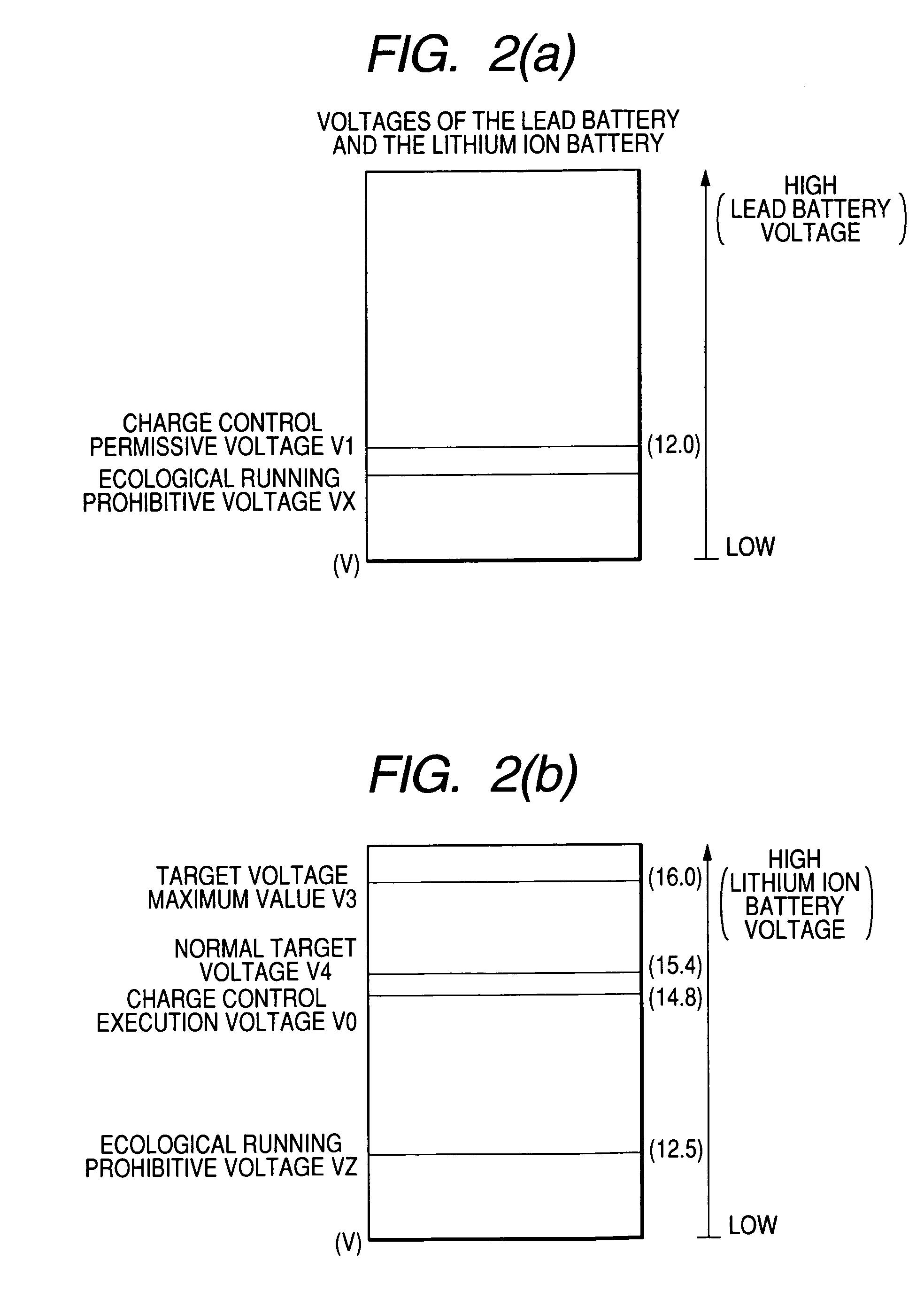
[0073]FIG. 4(a) is such as to show the invention and shows specifically an output voltage control by the DC / DC converter in the charge control on the lithium ion battery. In this embodiment, a target charge voltage value TLiV of the lithium ion battery is changed from the normal target voltage V4 to the target voltage maximum value V3 or the output voltage maximum value V3 of the DC / DC converter so as to reduce the charging time of the lithium ion battery while the lithium ion battery is charged, with the voltage value LiV of the lithium ion battery 2 being equal to or larger than the charge control execution voltage V0 and with the voltage value PbV of the lead battery 1 being equal to or larger than the charge control permissive voltage V1. In Addition, FIG. 4(b) is a time chart which shows a transition of the output voltage of the DC / DC converter according to a control procedure shown in FIG. 4(a).

[0074]In step 401, the voltage value LiV of the lithium ion battery and the voltage...
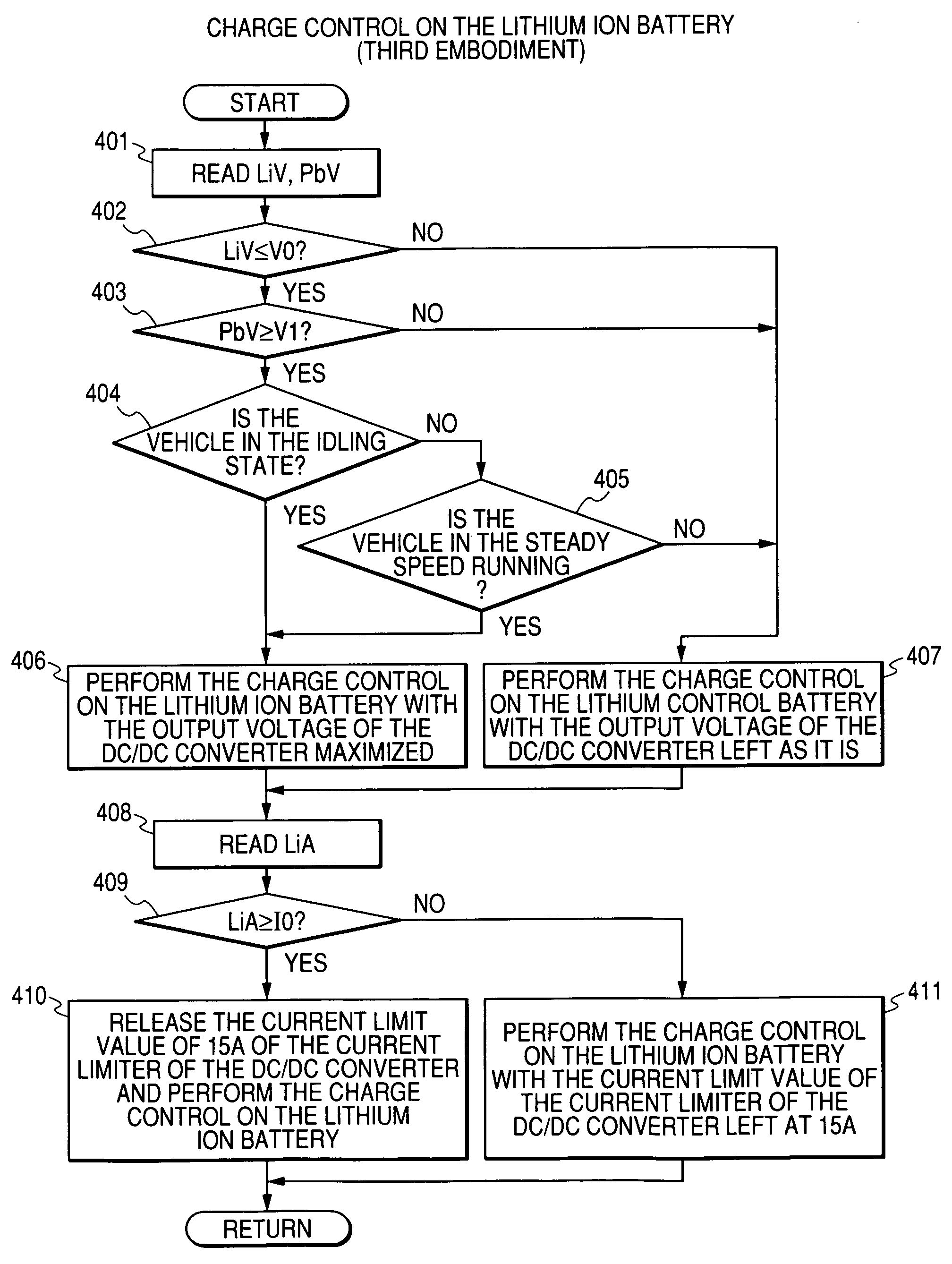
third embodiment

[0080]In the third embodiment, since, when the predetermined condition is established while the lithium ion battery is charged, the value of a voltage outputted then from the DC / DC converter becomes large and the value of a current which flows into the lithium ion battery through the DC / DC converter becomes large compared to those resulting while the lithium ion battery is charged normally, the lithium ion battery can be charged completely in a short period of time compared to the related-art case. As a result, the frequency of occurrence of the economical running is increased to thereby improve the fuel economy.

[0081]While, in the first embodiment, the example is described in which the current limit value of the current limiter of the DC / DC converter is released when the value of current which flows through the DC / DC converter becomes equal to or larger than I0, in reality, in the event that a state where the value of current which flows through the DC / DC converter equals the norma...


PUM


Abstract

A first buttery supplies power to an electrical load of a vehicle when an engine is in a normal operation. A second buttery supplies power to the electrical load of the vehicle when the engine is in an economical operation. A voltage regulator regulates voltages of the first buttery and the second buttery. A current limiter limits a current value flowing from the voltage regulator to the second battery to a limiting value. An engine stopping unit stops the engine when a first predetermined condition is established. An activator starts the engine when a second predetermined condition is established. A current detecting unit detects the current value when a second battery is charged. A changing unit changes a limiting value between a first limiting value and a second limiting value which is higher than the first limiting value according to the detected current value in a case where the voltage of the second battery is no more than a second predetermined value and the voltage of the first battery is no less than a first predetermined value.

Description

BACKGROUND OF THE INVENTION[0001]The present information relates to an engine control apparatus, a control method and a control system.[0002]Generally, in a vehicle on which an engine is installed, a starter motor is necessary for starting the engine, and this starter motor is driven by means of a chargeable lead storage battery (hereinafter, the storage battery will be referred to as a battery). In addition, a number of auxiliary machines (electric loads) such as lamps, an air conditioner and electric power window systems which are driven by the battery are installed on the vehicle as electric equipment. Then, in order to recover the battery capacity that has been discharged to start the engine and drive the auxiliary machines, a generator (an alternator) is installed on the vehicle which is driven by the engine to generate electric power so as to charge the battery with electric power so generated.[0003]On the other hand, in the vehicle on which the engine is installed, reducing a...

Claims


Application Information

Patent Timeline
Patent Type & Authority Patents(United States)
IPC IPC(8): B60W20/00
CPCH02J7/1423Y02T10/7005F02N11/0814F02N11/0866Y02T10/70
Inventor YAMAGUCHI, KAZUHI
Owner FUJITSU GENERAL LTD
Why Eureka
Try Eureka