Dual camera assembly for an imaging-based bar code reader

a bar code reader and bar code technology, applied in the direction of instruments, dynamo-electric converter control, sensing by electromagnetic radiation, etc., can solve the problems of high density 2d bar code imaging resolution and decoding, and increase the difficulty of successfully utilizing an imaging-based bar code reader, etc., to achieve high resolution

Active Publication Date: 2009-05-19
SYMBOL TECH LLC
View PDF3 Cites 160 Cited by
  • Summary
  • Abstract
  • Description
  • Claims
  • Application Information

AI Technical Summary

Problems solved by technology

There are two requirements that increase the difficulty of successfully utilizing an imaging-based bar code reader.
For many items, the available area where a bar code may be imprinted is limited.
However, deceasing feature size leads to problems in imaging resolution and decoding of high density 2D bar codes, such at PDF 417 and DataMatrix bar codes which utilize very small feature size.
Obviously, the higher the density of a target bar code, the more difficult it is for the imaging system to generate an image with sufficient clarity and resolution to permit successful decoding of the target bar code image.
If the bar code is moved closer to the reader imaging system, a size of the field of view FOV may become too small to image the entire bar code.
On the other hand, if the bar code is move away from the reader imaging system, the resolution of the imaged bar code may be inadequate to allow for successful decoding of the imaged bar code.
Because of the movement of a target bar code within the FOV during imaging, the resulting image of the bar code may exhibit distortion that renders the decoding process more difficult or impossible.
Characteristics of imaging systems that provide for the high resolution imaging necessary with high density 2D bar codes are different and often at odds with the characteristics of imaging systems that provide for successful imaging of moving, as opposed to stationary, bar codes.

Method used


Image

  • Dual camera assembly for an imaging-based bar code reader
  • Dual camera assembly for an imaging-based bar code reader
  • Dual camera assembly for an imaging-based bar code reader

Examples


second exemplary embodiment

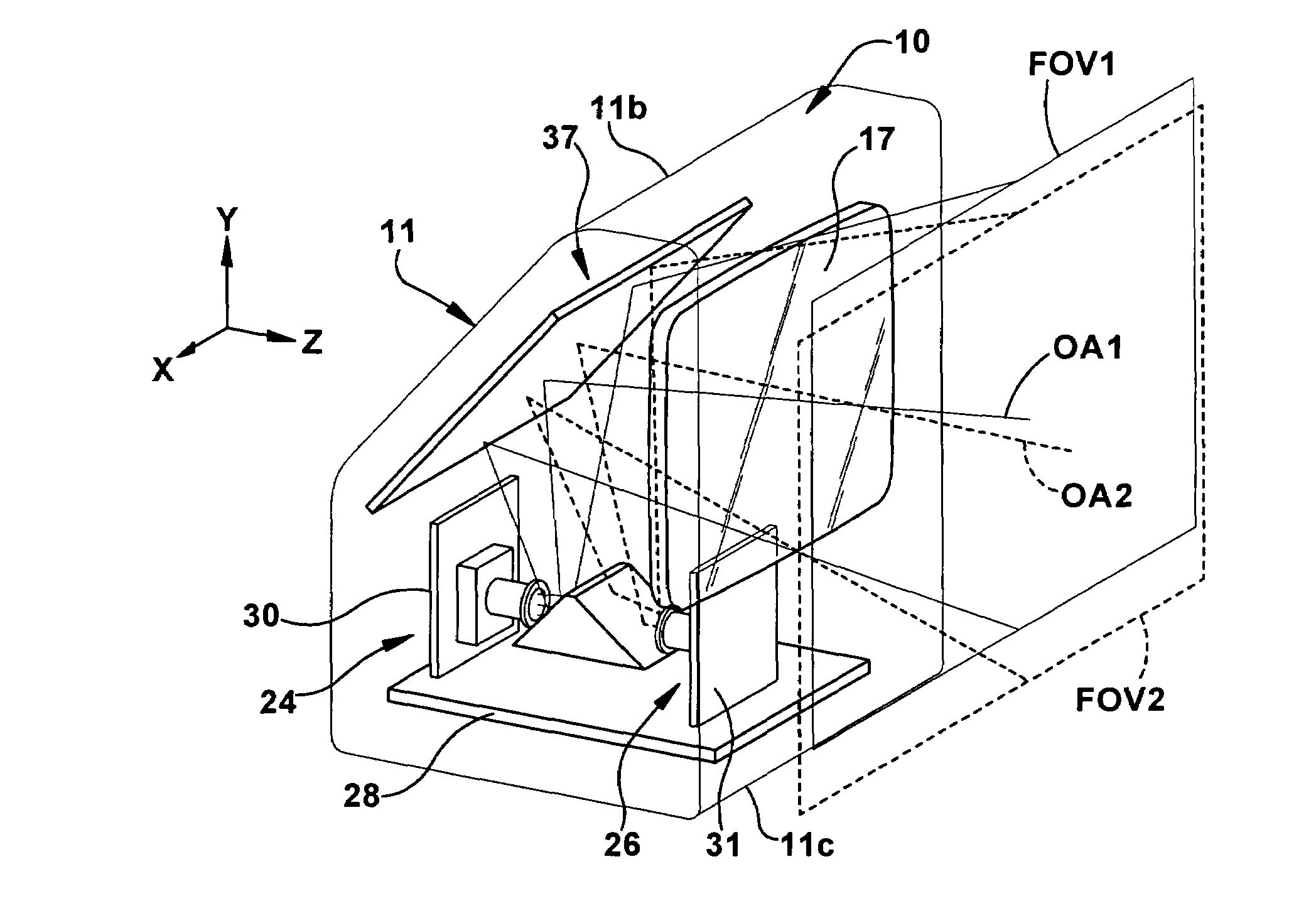
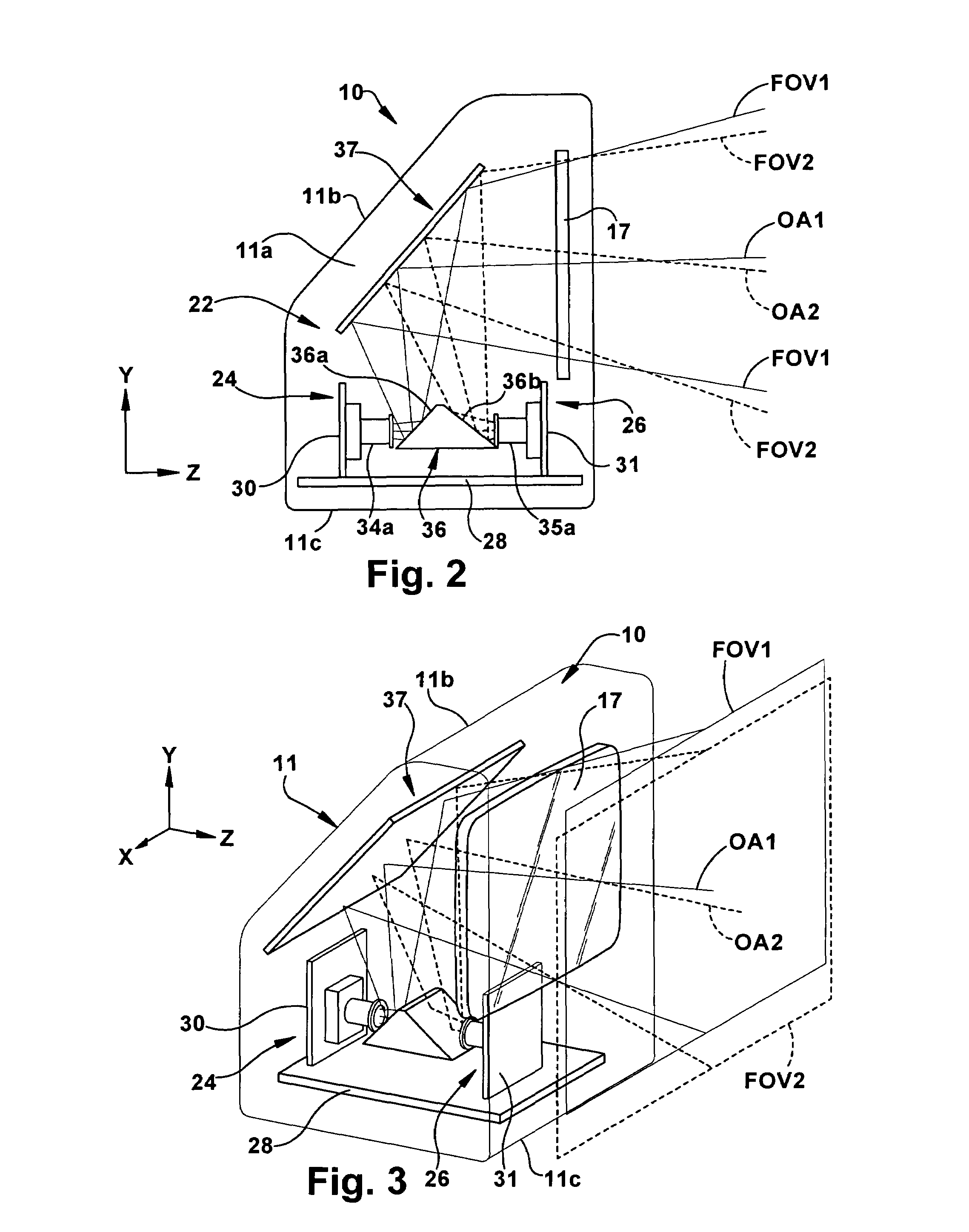
[0056]A second exemplary embodiment of an imaging-based bar code reader of the present invention is shown schematically at 100 in FIG. 5. The reader 100 includes a dual camera assembly 122 including a first camera module 124 having a first optical path or field of view FOV11 and a second camera module 126 having a second optical path or field of view FOV12. The first camera module 124 (which may be either the global shutter camera or the mega pixel camera) is mounted to a horizontally-oriented base PC board 128. The second camera module 126 is mounted on a PC board 131 that extends vertically from the base PC board 128.

[0057]The optical paths OA11, OA12 of the first and second camera modules 124, 126 within an interior region 111a of the housing 111 are different than in the first embodiment. The first camera module 124 is positioned in the housing 111 such that its field of view FOV11 intersects a larger first fold mirror 136 and is redirected to pass through the transparent window...

third exemplary embodiment

[0058]A third exemplary embodiment of an imaging-based bar code reader of the present invention is shown schematically at 200 in FIG. 6. The reader 200 includes a dual camera assembly 222 including a first camera module 224 having a first optical axis OA21 and first field of view FOV21 and a second camera module 226 having a second optical axis OA22 and second field of view FOV22. The first camera module 224 (which may be either the global shutter camera or the mega pixel camera) is mounted to a horizontally-oriented base PC board 228. The second camera module 226 is mounted on a PC board 231 that is at an acute angle with respect to the base PC board 228 such that the second optical axis OA22 is at an acute angle with respect to the first optical axis OA21.

[0059]This configuration eliminates the need for two fold mirrors. As can be seen, a single fold mirror is positioned to intersect and redirect the optical paths OA21, OA22 of the first and second camera modules 224, 226 within a...

fourth exemplary embodiment

[0060]A fourth exemplary embodiment of an imaging-based bar code reader of the present invention is shown generally at 310 in FIGS. 7 and 8. In this embodiment, the housing 311 is a pistol-shaped housing that is adapted to be used in a hands-free mode when inserted in a stand or docking station 312 that accepts a lower or boot 311a of a handle portion 311b of the housing 311. The reader 310 is also advantageously adapted to be used in a hand-held or portable mode in which it may be removed from the stand 312 by a user and carried around a facility such as a store or warehouse to read bar codes on products stocked on shelves or pallets.

[0061]When used in a hand-held mode, a trigger 311c is provided to allow the user to actuate the imaging system 320. A bottom of the boot 311a may include a magnetic switch 370 (such as the magnetic switch 70 described above with respect to the first embodiment) that changes states when removed from the stand 312 to let the imaging system 320 know whet...


PUM


Abstract

An imaging system (20) for an imaging-base bar code reader (10) having a housing (11) and a window (17). The imaging system (20) includes a dual camera assembly (22) having a first camera assembly (24) and a second camera assembly (26) mounted within the housing (11) to image a target object (14a, 14b). The first camera assembly (24) includes a first field of view (FOV1) and the second camera assembly (26) including a second field of view (FOV2). The imaging system (20) further includes a fold mirror (36, 37) and positioned within the bar code reader housing (11) to intersect and direct the field of view of at least one of the first and second camera assemblies (24, 26) such that the first and second fields of view (FOV1, FOV2) pass through the exit window (17) and are substantially congruent exterior of the housing (11).

Description

FIELD OF THE INVENTION[0001]The present invention relates to a dual camera assembly for an imaging-based bar code reader and, more particularly, to a dual camera assembly including a first camera assembly having a rolling shutter for reading high density two dimensional (2D) bar codes over an extended range and a second camera assembly having a global shutter for swipe reading of one dimensional (1D) and 2D bar codes.BACKGROUND ART[0002]Various electro-optical systems have been developed for reading optical indicia, such as bar codes. A bar code is a coded pattern of graphical indicia comprised of a series of bars and spaces of varying widths, the bars and spaces having differing light reflecting characteristics. Some of the more popular bar code symbologies include: Uniform Product Code (UPC), typically used in retail stores sales; Code 39, primarily used in inventory tracking; and Postnet, which is used for encoding zip codes for U.S. mail. Bar codes may be one dimensional (1D), i...

Claims


Application Information

Patent Timeline
Patent Type & Authority Patents(United States)
IPC IPC(8): G06K9/18H02P1/00G06V30/224
CPCG06K7/10722
Inventor BARKAN, EDWARD D.DRZYMALA, MARKBIANCULLI, THOMAS D.
Owner SYMBOL TECH LLC
Why Eureka
Try Eureka