
Reel and recording tape cartridge

a technology of reel and recording tape, applied in the field of reel, can solve problems such as easy disengagement of proportions and concern for strength

Active Publication Date: 2009-05-19
FUJIFILM CORP
View PDF11 Cites 15 Cited by
  • Summary
  • Abstract
  • Description
  • Claims
  • Application Information

AI Technical Summary

Benefits of technology

The present invention provides a reel and recording tape cartridge that can withstand damage even when dropped. The reel includes a hub that is securely held in place by a rotational detent member and an upper and lower circular cylinder portions that are welded together. This design prevents the hub from easily disengaging and sustaining damage. The recording tape cartridge includes the reel and a rotational detent member that regulates the movement of the hub. Overall, this invention improves the reliability and durability of the reel and recording tape cartridge.

Problems solved by technology

However, when the reel is dropped with the magnetic tape wound onto the hub, there is the possibility for the claw portion to be easily disengaged from the loop member and for the claw portion and the loop member to sustain damage, so that problems in terms of strength are of concern.

Method used


Image

  • Reel and recording tape cartridge
  • Reel and recording tape cartridge
  • Reel and recording tape cartridge

Examples


Embodiment Construction

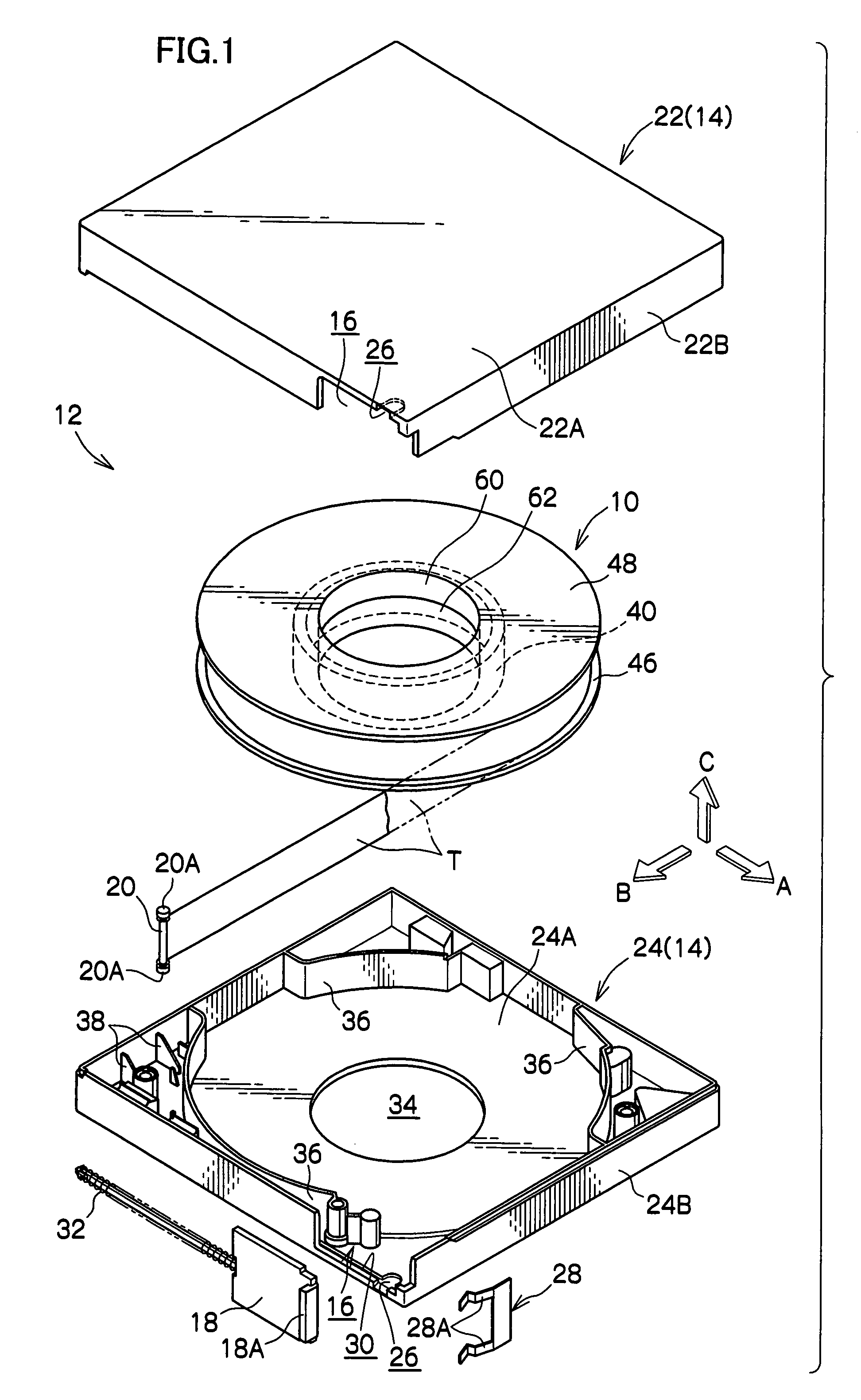
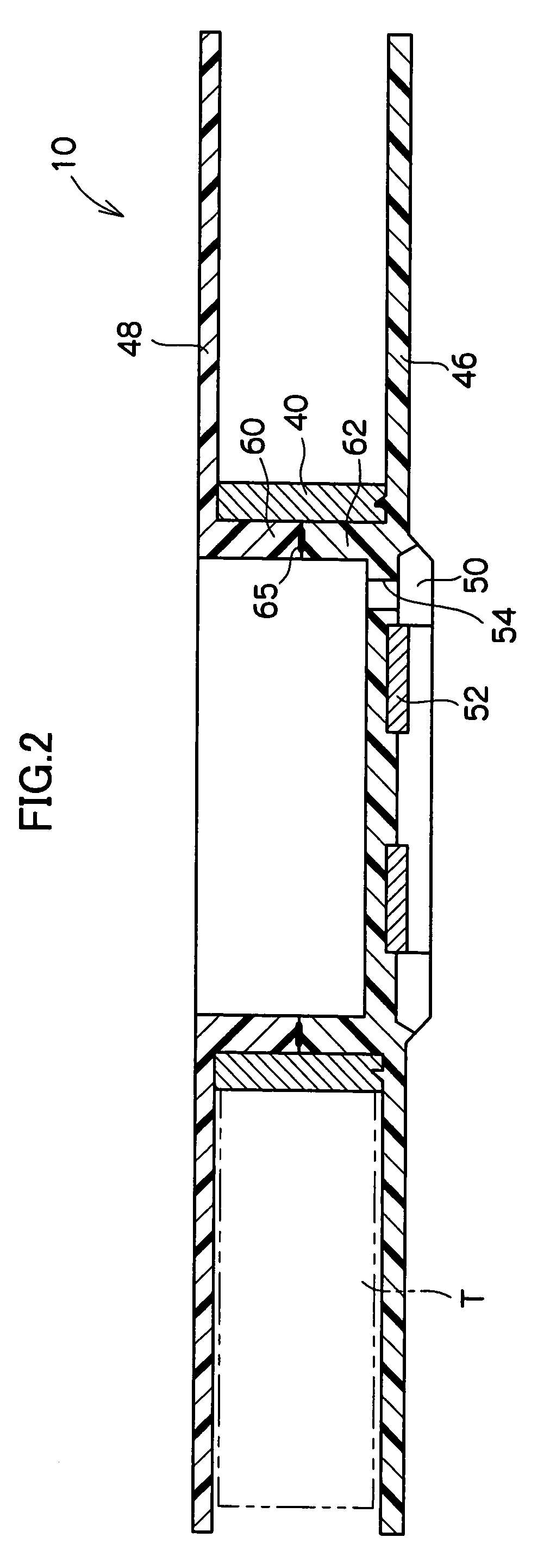
[0020]A reel 10 according to an exemplary embodiment of the present invention will be described with reference to FIG. 1 to FIG. 6. First, a schematic overall configuration of a recording tape cartridge 12 to which the reel 10 is applied will be described, and then the reel 10 will be described in detail. For the convenience of description, arrow A will represent the direction in which the recording tape cartridge 12 is loaded into a drive device and be referred to as a forward direction (front side), and arrow B and arrow C, which are orthogonal to the direction represented by arrow A, will respectively represent a rightward direction and an upward direction.

Configuration of the Recording Tape Cartridge

[0021]In FIG. 1, there is shown an exploded perspective view of the recording tape cartridge 12. The recording tape cartridge 12 is configured to include a case 14 and a single reel 10. The case 14 has a substantially rectangular shape when seen in plan view, and the reel 10 is rotat...


PUM

PropertyMeasurementUnit
heightaaaaaaaaaa
heightaaaaaaaaaa
heightaaaaaaaaaa

Abstract

A reel that includes: an upper flange and a lower flange that retain width direction edge portions of a recording tape; a lower circular cylinder portion disposed extending upward from an upper surface of the lower flange on the same circumference as the axial center of the lower flange; a hub that is fitted over the outside of the lower circular cylinder portion and around which the recording tape is wound; a rotational detent member that regulates movement of the hub in the circumferential direction with respect to the lower flange; and an upper circular cylinder portion that extends downward from an undersurface of the upper flange and is welded to an end surface of the lower circular cylinder portion such that the hub is interposed and held between the upper flange and the lower flange. A recording tape cartridge that includes this reel.

Description

CROSS-REFERENCE TO RELATED APPLICATION[0001]This application claims priority under 35 USC 119 from Japanese Patent Application No. 2006-123918 filed Apr. 27, 2007, the disclosure of which is incorporated by reference herein.BACKGROUND OF THE INVENTION[0002]1. Technical Field[0003]The present invention relates to a reel that winds recording tape such as magnetic tape and to a recording tape cartridge.[0004]2. Related Art[0005]As external storage media for computers and the like, recording tape cartridges are known which include a case housing a reel onto which, for example, a magnetic tape is wound. The reel includes a hub, which configures the axial center portion of the reel and around whose outer periphery the magnetic tape is wound, and an upper flange and a lower flange, which project outward in the radial direction from both axial direction ends of the hub.[0006]Conventionally, a recording tape cartridge has been known which includes a single reel onto which is wound recording ...

Claims


Application Information

Patent Timeline
Patent Type & Authority Patents(United States)
IPC IPC(8): G11B15/32
CPCG11B23/107
Inventor SUMIYA, YOSUKEASHIKAWA, TERUO
Owner FUJIFILM CORP
Learn More