Fiber optic cable spool

Inactive Publication Date: 2009-05-19
CISCO TECH INC
View PDF29 Cites 56 Cited by
  • Summary
  • Abstract
  • Description
  • Claims
  • Application Information

AI Technical Summary

Benefits of technology

[0010]It has been discovered that providing a spool with an S shaped groove connecting two circumferential pathways advantageously

Problems solved by technology

Improper handling of fiber optic cable during shipment and installation can damage the cable.
Twists or kinks in the cable can cause microcracks, whi

Method used


Image

  • Fiber optic cable spool
  • Fiber optic cable spool
  • Fiber optic cable spool

Examples


Example

The use of the same reference symbols in different drawings indicates identical items unless otherwise noted.

DETAILED DESCRIPTION

[0023]The following sets forth a detailed description of a mode for carrying out the invention. The description is intended to be illustrative of the invention and should not be taken to be limiting.

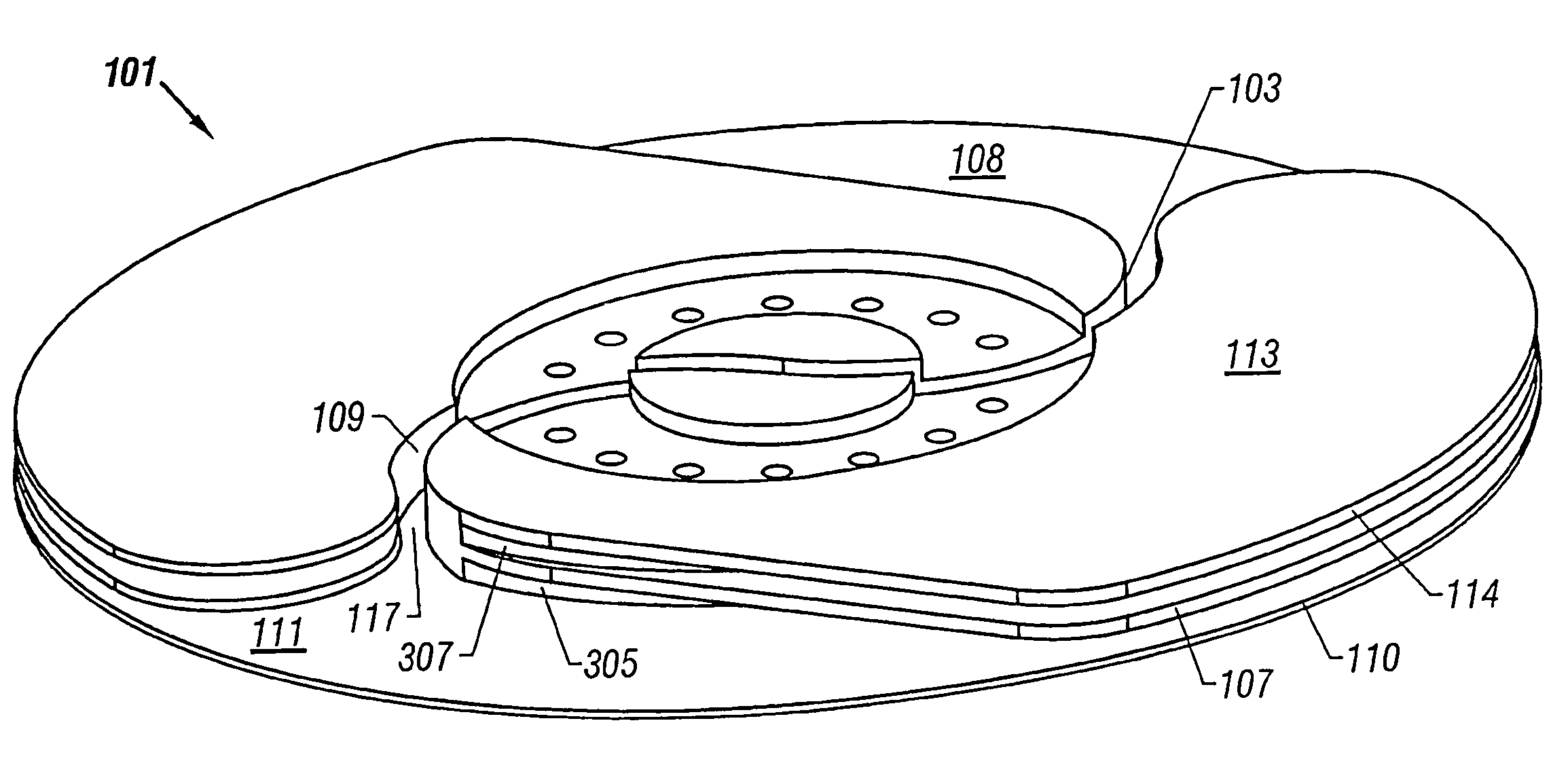
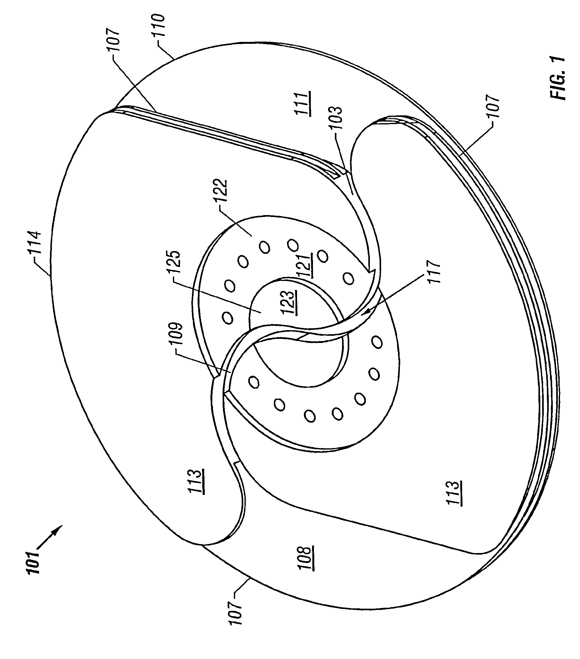
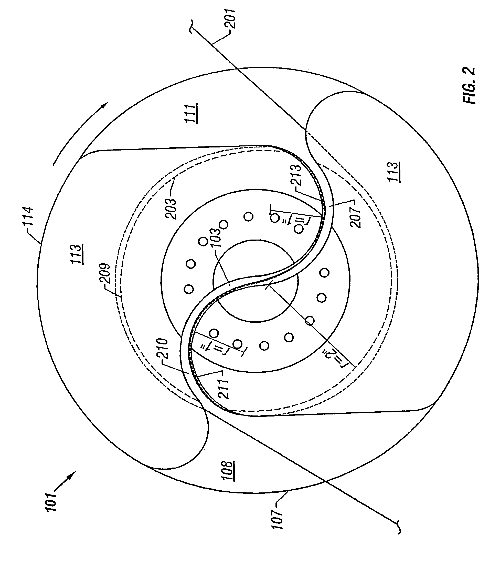
[0024]FIG. 1 is a perspective view of a fiber optic cable spool according to the present invention. Fiber optic cable spool 101 can be utilized for storing excess fiber optic cable in a communication systems such as, e.g., a wavelength router-class, optical cross connect for a communications network.

[0025]Spool 101 includes an S shaped cable pathway 103 that extends through a middle region of spool 101. S shaped cable pathway 103 connects a first circumferential cable pathway with a second circumferential cable pathway. Circular inner wall structure 107 separates the first circumferential cable pathway from the second circumferential cable pathway. For the embo...


PUM


Abstract

A spool for holding cable is disclosed. The spool has an S shaped cable pathway for connecting a first circumferential cable pathway with a second circumferential cable pathway. In one embodiment, the spool includes an S shaped groove extending through the middle portion of the spool to define the S shaped cable pathway. In one embodiment, the radiuses of the arc pathways of the S shaped cable pathway are designed to meet the minimum bending requirements of the cable to be stored on the spool. In one embodiment, cable is stored in the spool by first inserting a middle portion of cable to be stored in the spool in S shaped cable pathway and then rotating the spool in a first direction.

Description

[0001]This application is a continuation of, and claims the benefit of priority based on, U.S. patent application Ser. No. 09 / 590,811 now U.S. Pat. No. 6,511,009 B1, entitled “Fiber Optic Cable Spool” filed Jun. 9, 2000 issued Jan. 28, 2003, and naming Carl G. Harrison and Michael A. Mandry as inventors. The above-referenced patent is hereby incorporated by reference herein in its entirety.BACKGROUND OF THE INVENTION[0002]1. Field of the Invention[0003]This invention relates in general to communication systems and in particular to a spool for storing communications cable.[0004]2. Description of the Related Art[0005]Fiber optic cables are utilized in communications systems for carrying information between communication sources and sinks. An example of a communications system that utilizes fiber optic cable is an optical cross connect for a communications network.[0006]Fiber optic cable typically includes at least one glass core for optical, high bandwidth transmission of information....

Claims


Application Information

Patent Timeline
IPC IPC(8): B65H75/38B65H75/14G02B6/00G02B6/44
CPCB65H75/14G02B6/4457B65H2701/32G02B6/4453
Inventor HARRISON, CARL G.MANDRY, MICHAEL A.
Owner CISCO TECH INC
Why Eureka
Try Eureka