Illuminated visor vanity

a technology for visors and vanity mirrors, which is applied in the field of vehicle sun visors, can solve the problems of switching to discontinue energizing the light source and switching to energize the light sour

Inactive Publication Date: 2009-05-19
INT AUTOMOTIVE COMPONENTS GRP NORTH AMERICA INC
View PDF61 Cites 25 Cited by
  • Summary
  • Abstract
  • Description
  • Claims
  • Application Information

AI Technical Summary

Benefits of technology

[0015]In yet another object of the invention, The visor vanity may include a mirror cover mounted to the bezel for covering or uncovering the vanity mirror, wherein movement of the mirror cover into the uncovering position causes the switch to energize the light source.

Problems solved by technology

In such case, movement of the mirror cover into the uncovering position may cause the switch to energize the light source.
Moreover, movement of the mirror cover into the covering position may cause the switch to discontinue energizing the light source.

Method used


Image

  • Illuminated visor vanity
  • Illuminated visor vanity
  • Illuminated visor vanity

Examples


Embodiment Construction

)

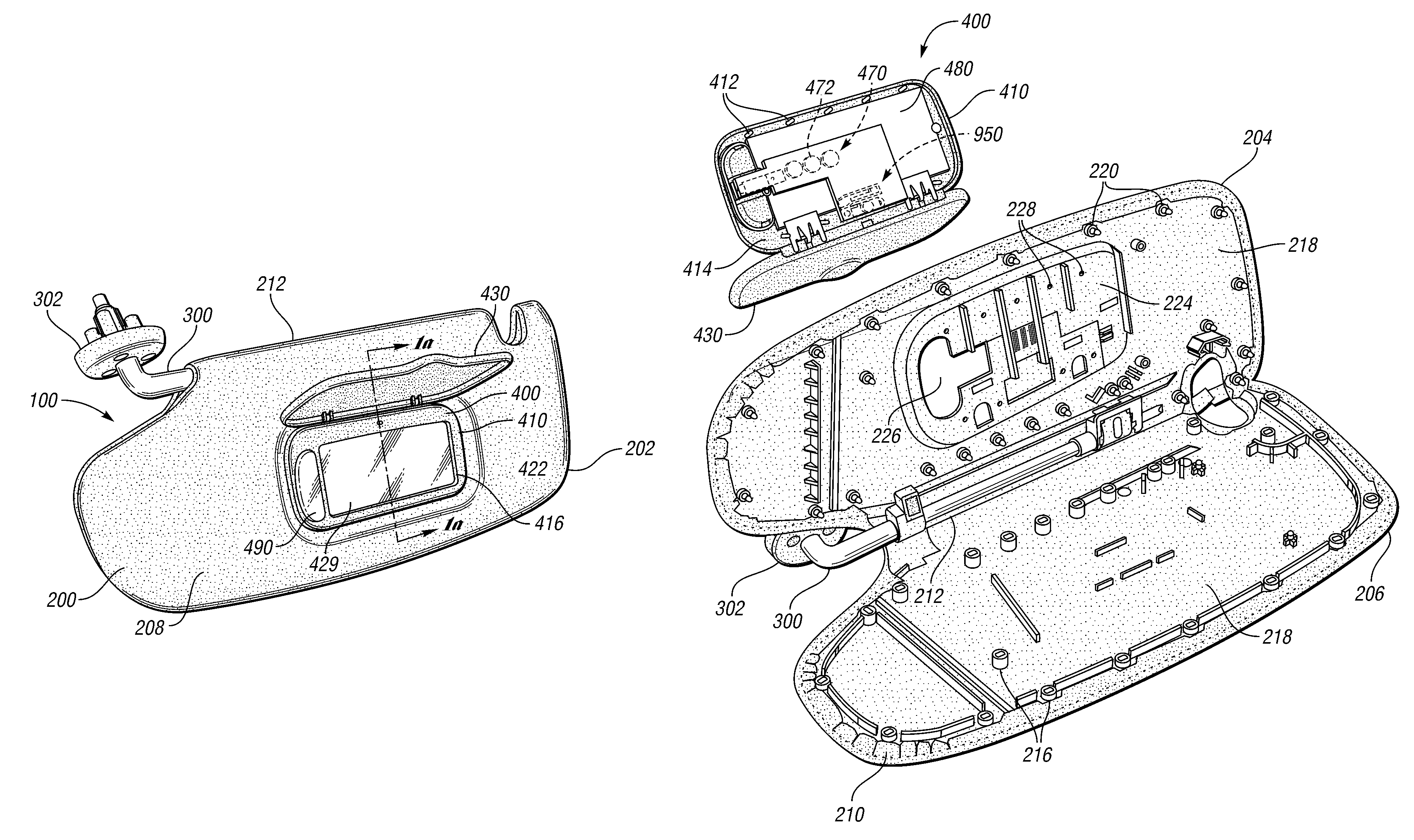
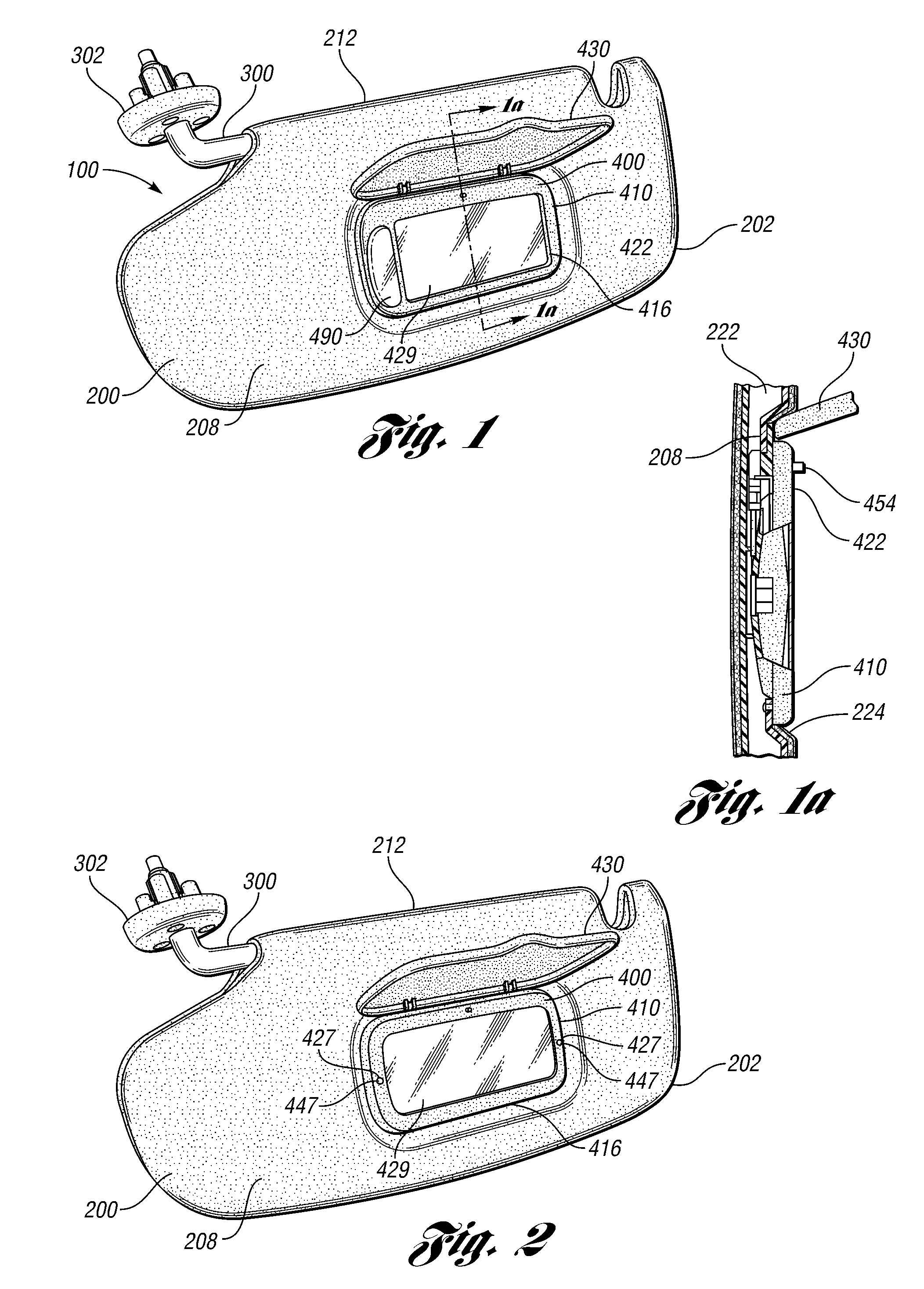
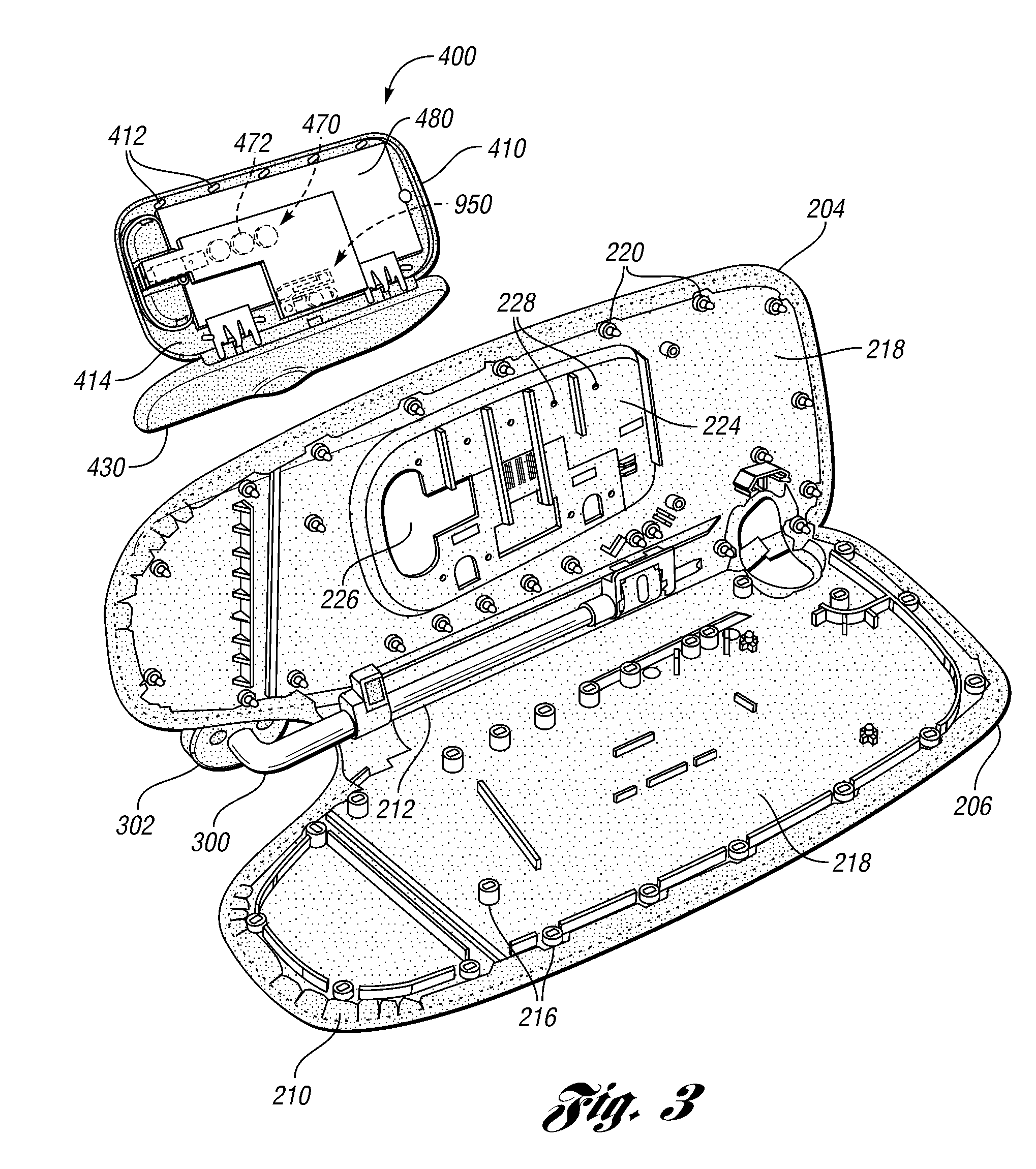
[0024]Referring to FIG. 1, a visor assembly 100 includes a visor 200 and a visor arm 300 having a visor bracket 302 of a conventional design.

[0025]The visor arm 300 is typically mounted to the visor bracket 302 which in turn may be mounted to any suitable mounting surface, such as the sheet metal of the vehicle roof (not shown). The visor arm 300 is typically pivotally connected to the visor bracket 302 such that the visor arm 300 together with the visor 200 may be moved into desired positions. For example, the visor arm 300 may typically be pivoted at the visor bracket 302 such that the visor 200 may be moved into positions such as adjacent to the front or side windows of a vehicle. Such brackets and pivotal connections are well known in the art and will not be described in further detail here.

[0026]The visor 200 is preferably mounted to the visor arm 300 via a torque control such that the visor 200 may be rotated relative to the visor arm 300. Such a torque control is preferably ...


PUM


Abstract

A visor vanity for use in a vehicle includes a vanity mirror, a light source for providing illumination to the user of the mirror or for other purposes, an energy source independent of the vehicle's electrical system for energizing the light source, a switch for causing light source to be energized by the independent power source or de-energized, and a timer for de-energizing the light source after a certain time period has passed so as to minimize depletion of the independent energy source. The light source may comprise one or more LEDs.

Description

BACKGROUND OF THE INVENTION[0001]1. Field of the Invention[0002]The present invention relates generally to vehicle sun visors having a vanity mirror and a light source for providing illumination to the user of the visor.[0003]2. Background Art[0004]Vehicles, such as automobiles and trucks, commonly employ sun visors. Such visors typically include a vanity mirror and a light source for providing illumination to the user of the vanity mirror. The light source is typically energized by the vehicle's electrical system. In so doing, electrical conduit (wiring) is required to be run from the electrical system of the vehicle to such vanity light source. Such electrical conduits are typically run through the support arm of the visor.[0005]An energy source independent from the vehicle electrical system, such as a battery, can be located within the visor vanity itself for energizing the light source. (see, e.g., U.S. Pat. No. 6,499,868) This eliminates the labor and material costs required in...

Claims


Application Information

Patent Timeline
Patent Type & Authority Patents(United States)
IPC IPC(8): B60Q3/02
CPCB60J3/0282B60Q3/0226B60Q3/0293B60Q3/0296Y10S362/80B60Q3/82B60Q3/252B60Q3/80
Inventor NICOLA, KIRK M.CARPENTER, JOEL D.HOBSON, JAMES J.
Owner INT AUTOMOTIVE COMPONENTS GRP NORTH AMERICA INC
Why Eureka
Try Eureka