Ring mechanism biased to closed and locked position

a ring mechanism and locking technology, applied in the field of ring binder mechanism, can solve the problems of difficult pivoting of the hinge plate through the coplanar position (180°) and the need for substantial housing spring force to hold the closed ring members together

Inactive Publication Date: 2009-05-19
WORLD WIDE STATIONARY MFG CO LTD
View PDF171 Cites 44 Cited by
  • Summary
  • Abstract
  • Description
  • Claims
  • Application Information

AI Technical Summary

Benefits of technology

[0005]Accordingly, there is a need for an efficient ring binder mechanism that readily locks when ring members close for retaining loose-leaf pages and has ring members that easily open and close.
[0008]Other features of the invention will be in part apparent and in part pointed out hereinafter.

Problems solved by technology

One drawback to these typical ring binder mechanisms is that a substantial housing spring force is required to hold the closed ring members together.
When the ring members close, the housing spring force snaps the ring members together rapidly and with a force that might cause fingers to be pinched between the ring members.
In addition, the housing spring force makes pivoting the hinge plates through the coplanar position (180°) difficult such that it is hard to both open and close the ring members.
Another drawback of typical ring binder mechanisms is that when the ring members are closed, they do not positively lock together.
So if the mechanism is accidentally dropped, the ring members may unintentionally open.
Still another drawback of typical mechanisms is that over time the housing may begin to permanently deform, reducing its ability to uniformly clamp the ring members together and possibly allowing gaps to form between closed ring members.
Failure to do this could result in the rings inadvertently opening and pages falling out.

Method used


Image

  • Ring mechanism biased to closed and locked position
  • Ring mechanism biased to closed and locked position
  • Ring mechanism biased to closed and locked position

Examples


Embodiment Construction

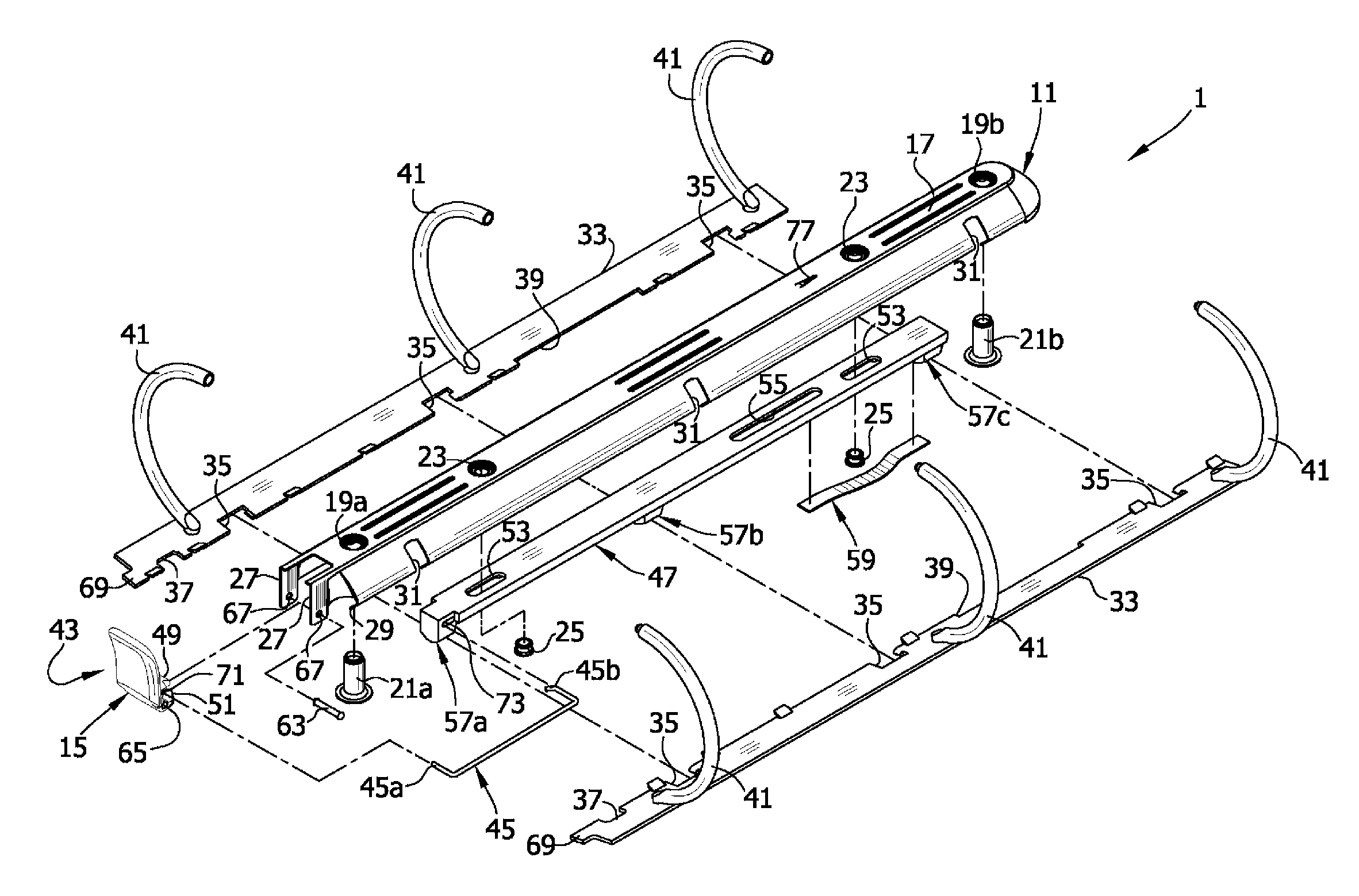
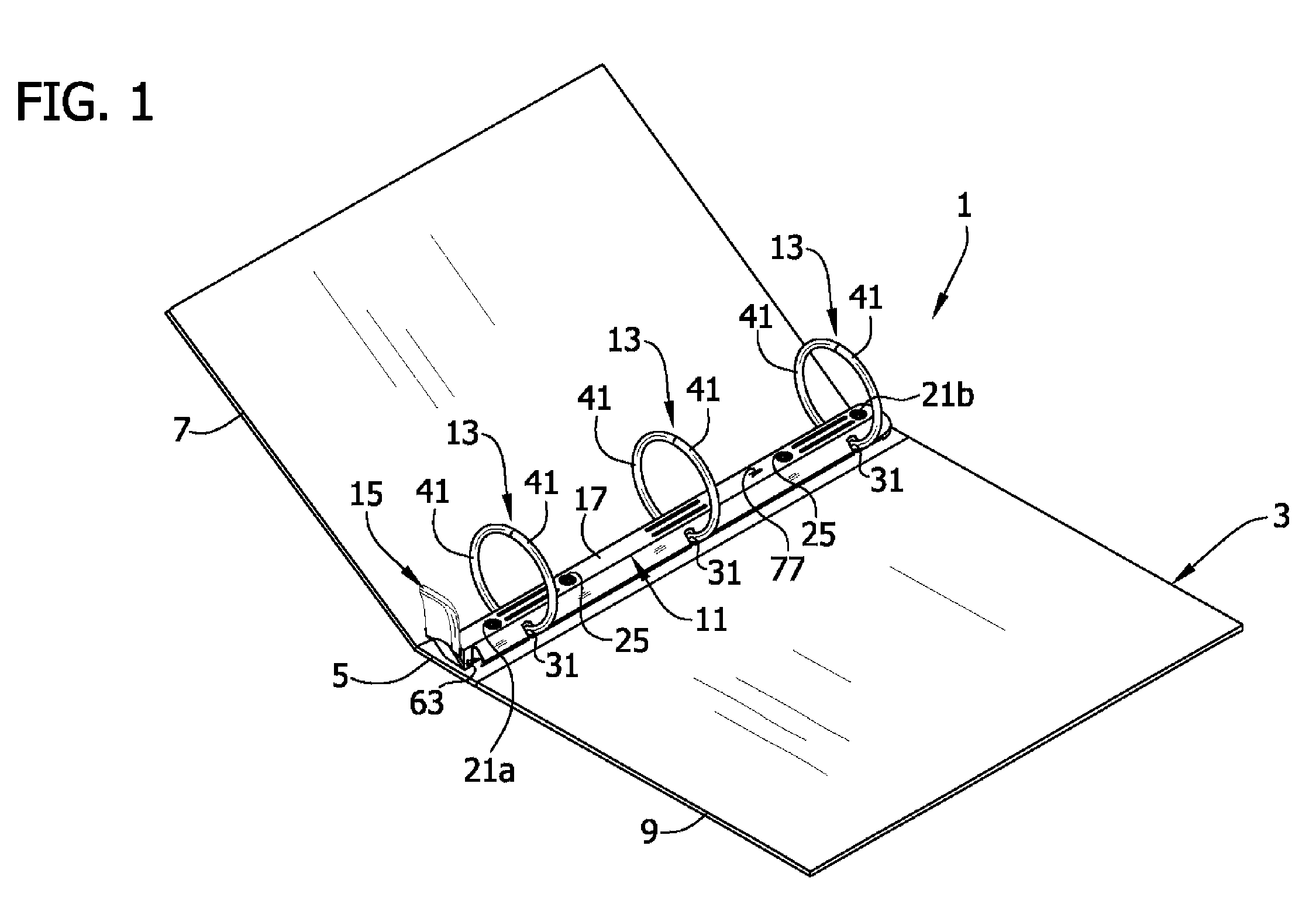
[0019]Referring now to the drawings, FIG. 1 shows a ring binder mechanism of the invention generally at reference numeral 1. The mechanism is shown mounted on a notebook, designated generally by reference numeral 3, and is capable of retaining loose-leaf pages (not shown) in the notebook. In particular, mechanism 1 is shown mounted on spine 5 of notebook 3 having front cover 7 and back cover 9 hingedly attached to the spine for moving to selectively cover or expose retained pages.

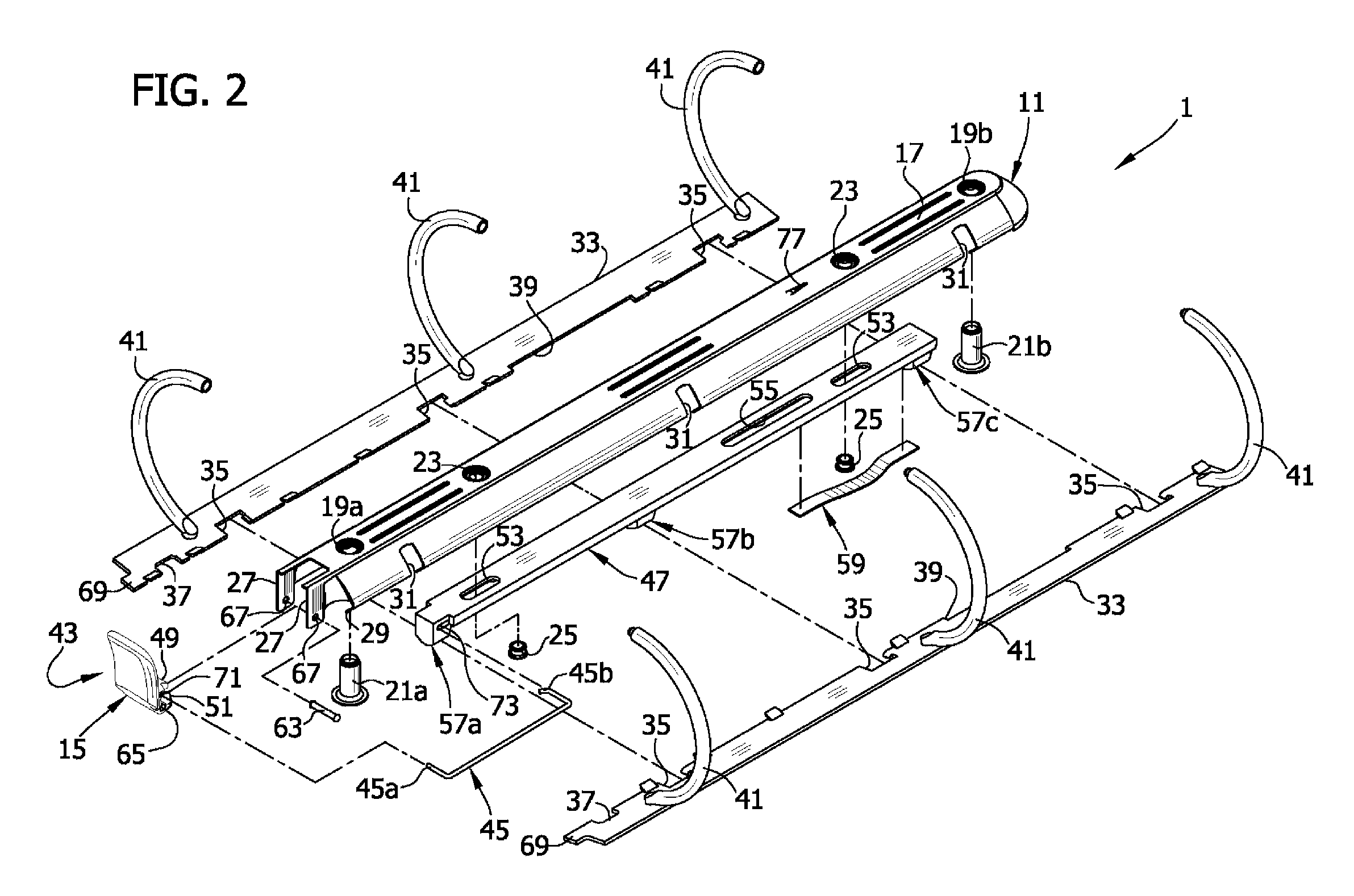
[0020]As can be seen, mechanism 1 includes a housing, designated generally by reference numeral 11, supporting three rings, each designated generally by reference numeral 13. Each ring includes two ring members, each designated by reference number 41, that will be described more hereinafter. A lever (broadly, “actuator”), designated generally by reference numeral 15, is shown pivotally mounted on one longitudinal end of housing 11 and can move ring members 41 of rings 13 between a closed position and an ope...


PUM


Abstract

A ring binder mechanism that retains loose-leaf pages and has ring members that readily lock together in a closed position, preventing accidental opening of the ring members and loss of pages. The mechanism comprises a housing that supports two hinge plates for pivoting motion that brings the ring members to either an open position or the closed position. The mechanism further comprises a control structure supported by the housing for causing the pivoting motion of the hinge plates. A spring plate is engageable with the control structure for urging the control structure to move toward a position blocking pivoting motion of the hinge plates when the ring members move to the closed position.

Description

BACKGROUND OF THE INVENTION[0001]This invention relates to a ring binder mechanism for retaining loose-leaf pages, and in particular to an improved mechanism for opening and closing ring members and for readily and securely locking closed ring members together.[0002]As is known in the art, a typical ring binder mechanism retains loose-leaf pages, such as hole-punched pages, in a file or notebook. It has multiple rings each including two half ring members capable of selectively opening to add or remove pages, or selectively closing to retain pages and allow them to move along the ring members. The ring members mount on two adjacent hinge plates that join together about a pivot axis for pivoting movement within an elongated housing. The housing loosely holds the hinge plates so they may pivot relative to the housing. The undeformed housing is slightly narrower than the joined hinge plates when the hinge plates are in a coplanar position (180°). So as the hinge plates pivot through thi...

Claims


Application Information

Patent Timeline
Patent Type & Authority Patents(United States)
IPC IPC(8): B42F3/02B42F13/02B42F3/04B42F13/12B42F3/00
CPCB42F13/26
Inventor CHENG, HUNG YU
Owner WORLD WIDE STATIONARY MFG CO LTD
Why Eureka
Try Eureka