Electrical connector with improved wire termination arrangement

Active Publication Date: 2009-05-19
HON HAI PRECISION IND CO LTD
View PDF17 Cites 61 Cited by
  • Summary
  • Abstract
  • Description
  • Claims
  • Application Information

AI Technical Summary

Benefits of technology

[0013]Accordingly, an object of the present invention is to p

Problems solved by technology

However, under a circumstance transmitting an audio or video file, which is always up to hundreds MB, even to 1 or 2 GB, currently transmission rate of USB is not sufficient.
However, these non-USB protocols are not used as broadly as USB protocols.
For example, while th

Method used


Image

  • Electrical connector with improved wire termination arrangement
  • Electrical connector with improved wire termination arrangement
  • Electrical connector with improved wire termination arrangement

Examples


third embodiment

[0032]Within the following description in accordance with the first, second and third embodiment of the present invention, a standard USB connector, plug, and signaling all refer to the USB architecture described within the Universal Serial Bus Specification, 2.0 Final Draft Revision, Copyright December, 2002, which is hereby incorporated by reference herein. USB is a cable bus that supports data exchange between a host and a wide range of simultaneously accessible peripherals. The bus allows peripherals to be attached, configured, used, and detached while the host and other peripherals are in operation. This is referred to as hot plugged.

first embodiment

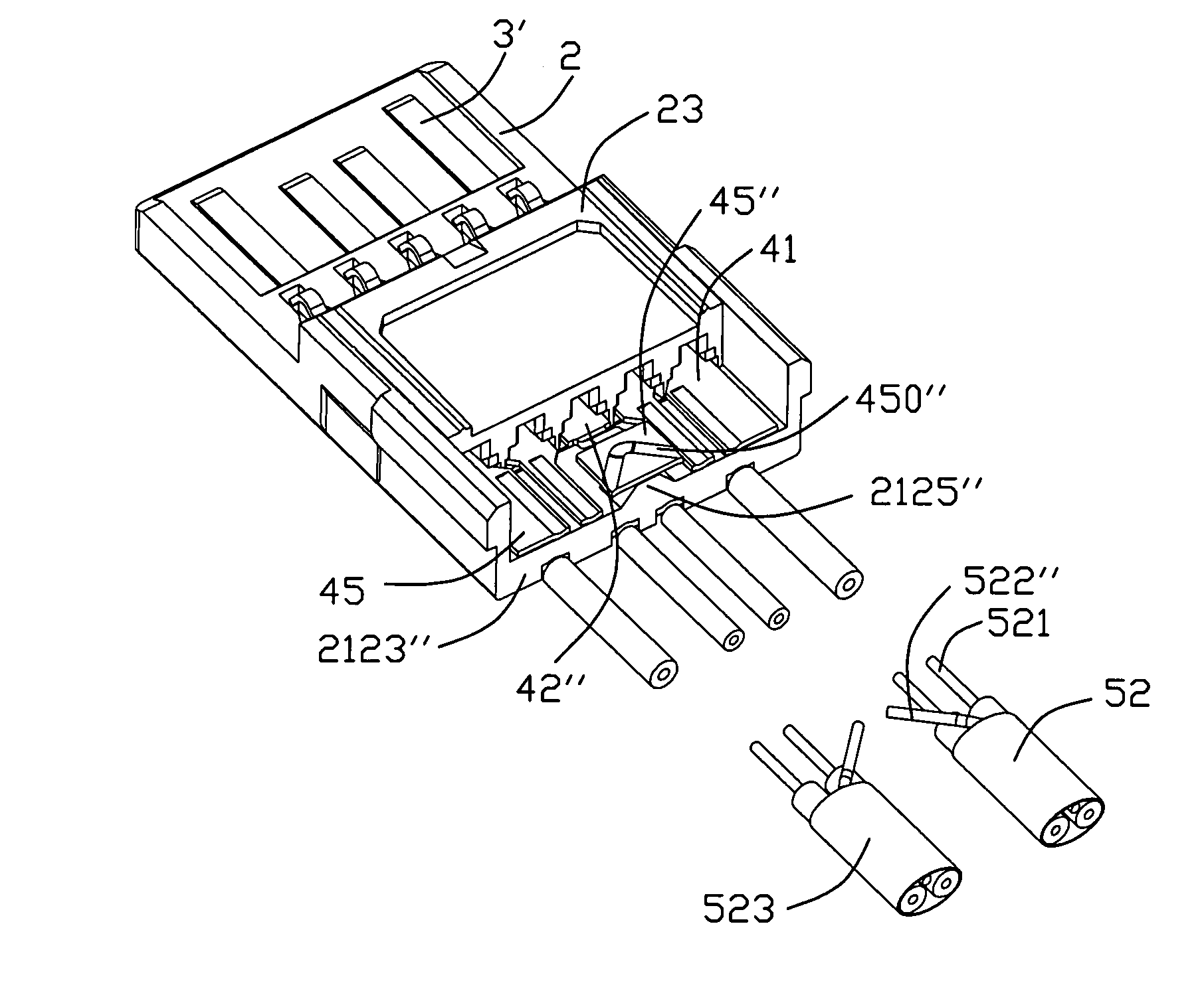
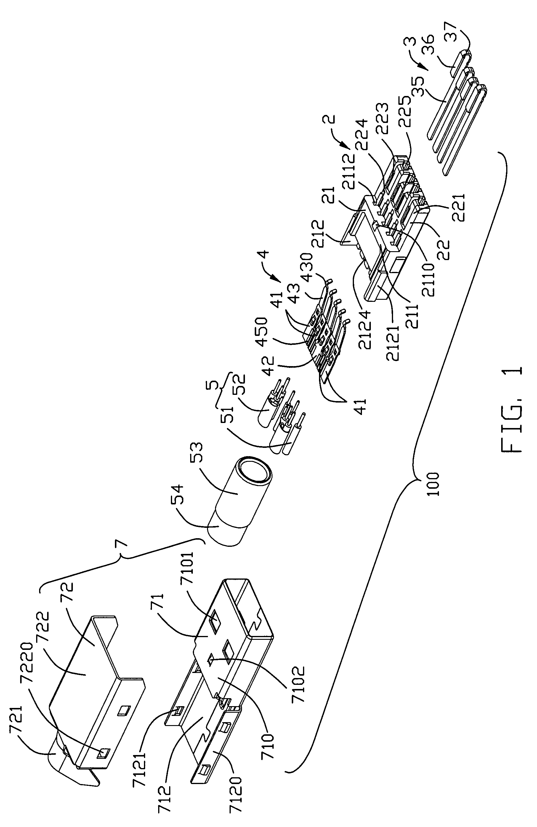
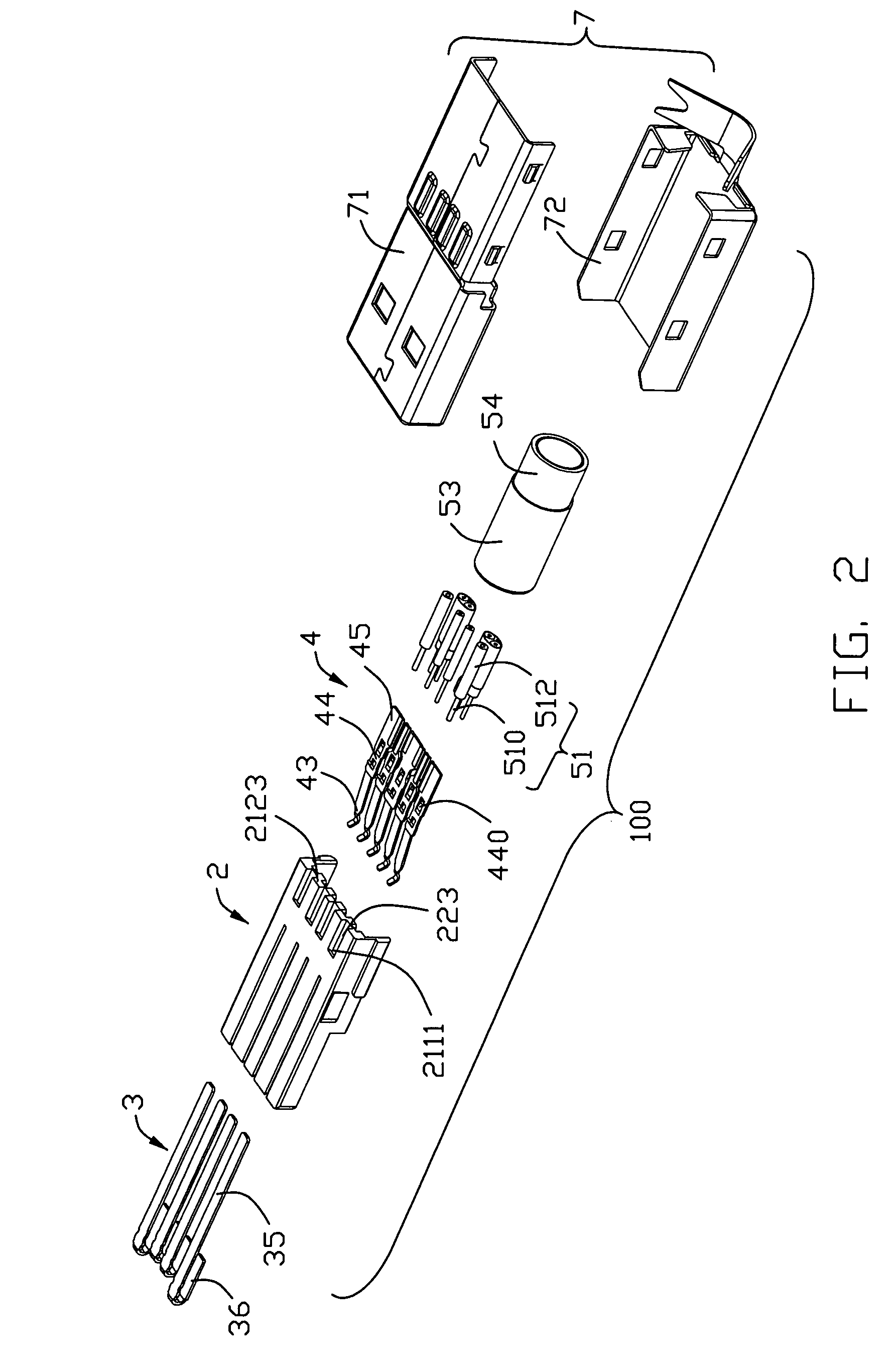
[0033]Referring to FIGS. 1-6, an electrical connector 100, that is a USB plug 100, according to the present invention is disclosed. The USB plug 100 comprises an insulative housing 2 which has an insulative base portion 21 and an insulative tongue portion 22 extending from the insulative base portion 21 in a front-to-rear direction, a first set of contacts 3 and a second set of contacts 4 supported in the insulative housing 2, and a metal shell 7 enclosing the insulative housing 2 and the contacts 3, 4. Besides, a cable 5 is provided to have first and second sets of wires 51, 52 to electrically connect with the contacts 3, 4. An outer jacket 53 is provided to bound the first and second sets of wires 51, 52 with a metal braid layer 54 formed by wires 51, 52 electrically connecting the metal shell 7 to provide shielding function. In order to provide a strong structure of the USB plug 100, an outer insulative cover 6 is over molded on a rear section of the insulative housing 2 together...


PUM


Abstract

An electrical connector (100) includes an insulative housing (2) extending in a front-to-back direction, a conductive shell (7) enclosing the insulative housing and cooperating with the insulative housing to define a receiving cavity (101) adapted for receiving a complementary connector, a first set of contacts (3) held in the insulative housing for transmitting a first kind of signals, a second set of contacts (4) held in the insulative housing and comprising two pairs of differential contacts (41) respectively for transmitting and receiving a second kind of signals and a grounding contact (42), a first set of wires (51) and a second set of wires (52). Each first contact includes a contacting section (36) exposed in the receiving cavity and a tail section (35) extending rearward from the contacting section. Each of the second set of contacts includes a contacting section (43) exposed in the receiving cavity and a tail section (45) extending rearward form the contacting section. The first set of wires are aligned in one row and have inner conductors (510) electrically connecting with the tail sections of the first set of contacts. The second set of wires are aligned in one row and include a pair of differential pairs (521) electrically connecting with the two pairs of differential contacts for transmitting and receiving the second kind of signals and at least one grounding conductor (522) electrically connecting with the grounding contact.

Description

CROSS-REFERENCE TO RELATED APPLICATIONS[0001]This application is related to U.S. patent application Ser. No. 11 / 818,100, filed on Jun. 13, 2007 and entitled “EXTENSION TO UNIVERSAL SERIAL BUS CONNECTOR WITH IMPROVED CONTACT ARRANGEMENT”, and U.S. patent application Ser. No. 11 / 982,660 filed on Nov. 2, 2007 and entitled “EXTENSION TO ELECTRICAL CONNECTOR WITH IMPROVED CONTACT ARRANGEMENT AND METHOD OF ASSEMBLING THE SAME”, both of which have the same assignee as the present invention.BACKGROUND OF THE INVENTION[0002]1. Field of the Invention[0003]The present invention relates to an electrical connector, more particularly to an electrical connector in accordance with standard Universal Serial Bus (USB) 3.0 connector.[0004]2. Description of Related Art[0005]Recently, personal computers (PC) are used of a variety of techniques for providing input and output. Universal Serial Bus (USB) is a serial bus standard to the PC architecture with a focus on computer telephony interface, consumer ...

Claims


Application Information

Patent Timeline
IPC IPC(8): H01R13/648
CPCH01R13/58
Inventor TSAO, PEIYI, CHONGCHEN, KUAN-YUBIDDLE, GARY E.
Owner HON HAI PRECISION IND CO LTD
Why Eureka
Try Eureka