Motor driving apparatus, motor driving method and disk driving apparatus
a technology of motor driving and disk driving, which is applied in the direction of motor/generator/converter stopper, electronic commutator, dynamo-electric converter control, etc., can solve the problems of increased cost, environmental resistance, motor remains stopped, and erroneous operation, and achieve reliable motor start
- Summary
- Abstract
- Description
- Claims
- Application Information
AI Technical Summary
Benefits of technology
Problems solved by technology
Method used
Image
Examples
embodiment 1
1. Configuration of Motor Driving Apparatus
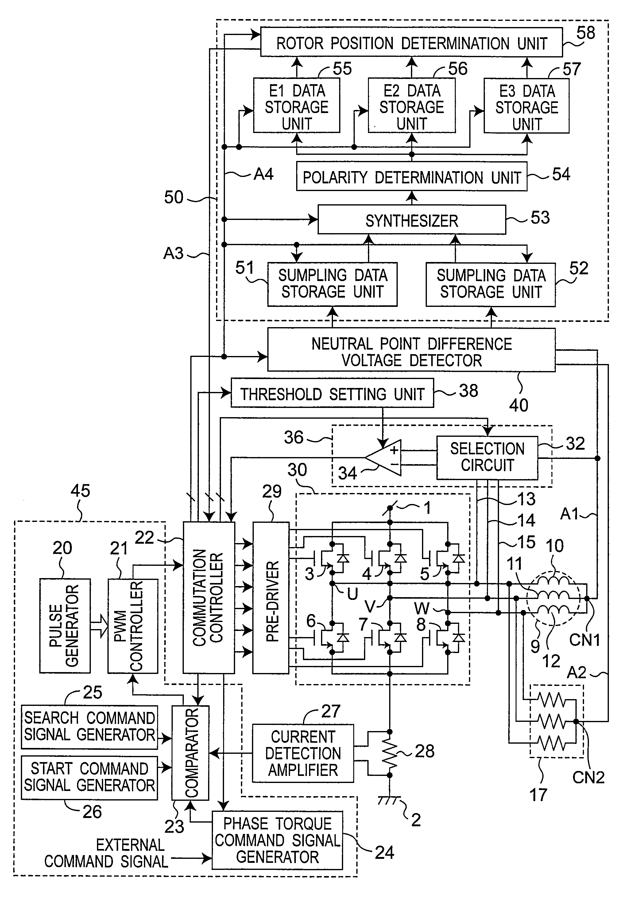
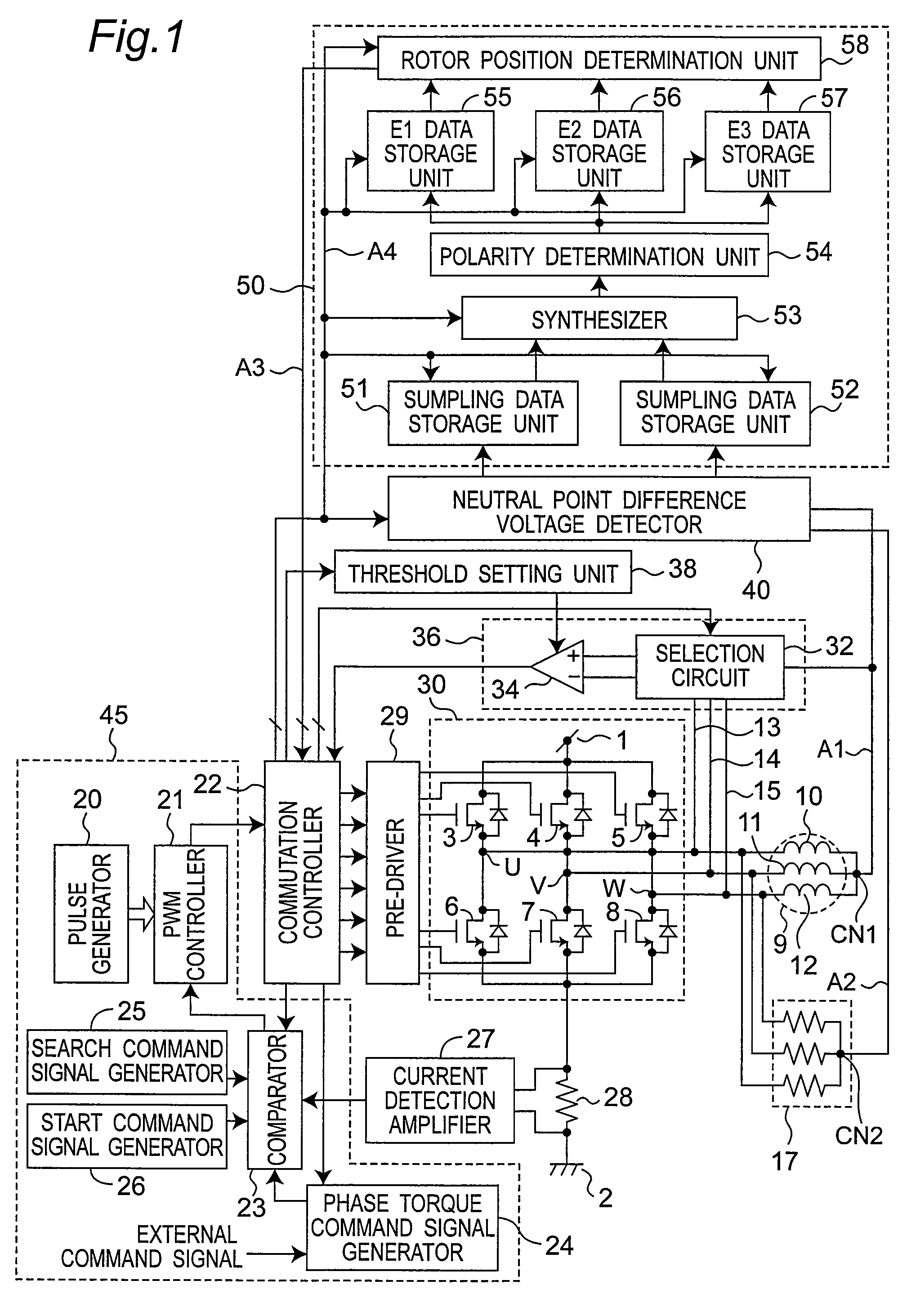
[0051]FIG. 1 shows a circuit configuration of a motor driving apparatus according to the present invention. The motor driving apparatus is a device for driving a motor 9.
[0052]The motor 9 includes a stator having coils 10 to 12 of three phases, a U-phase, a V-phase and a W-phase, and a rotor which is rotated by a rotating magnetic field generated in the stator. Although a three-phase motor is used as an example of the motor 9 in the present embodiment, an N-phase motor (N is an integer not smaller than 4) may be used. A U-phase coil 10, a V-phase coil 11 and a W-phase coil 12 have common connection at an actual neutral point CN1.
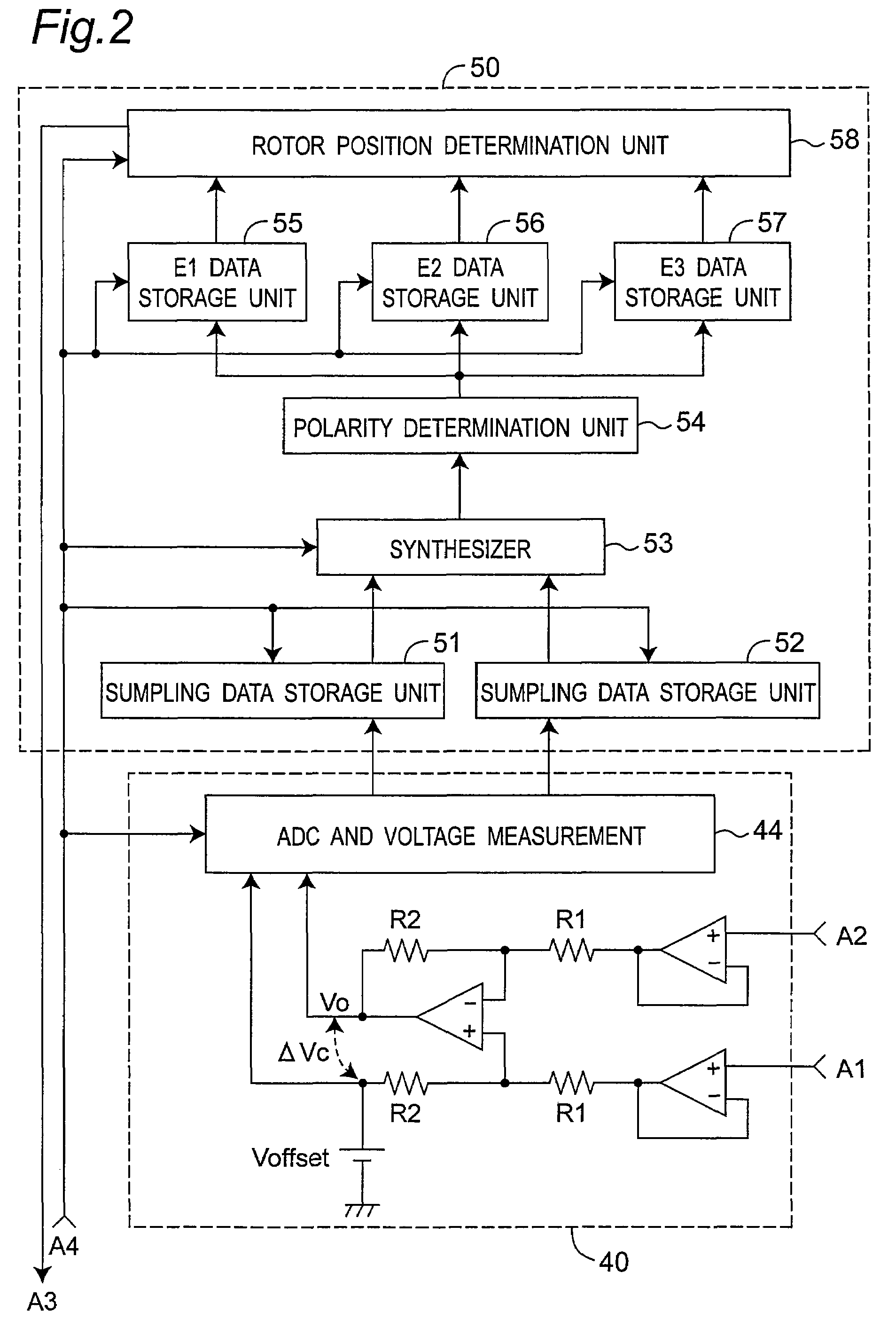
[0053]The motor driving apparatus supplies a drive power of the motor 9, and has an inverter circuit 30 including a plurality of switching elements 3 to 8, a pre-driver 29 for outputting a drive signal of each of the switching elements 3 to 8 in the inverter circuit 30, a commutation controller 22 for outputting to ...
embodiment 2
[0234]In Embodiment 1, the method for setting start conduction phases of the rotation start pulse is described by reference to FIG. 8. In the present embodiment, another example thereof is described.
[0235]FIG. 17A shows another example. In the example of FIG. 17A, polarity determination of E1, E2 and E3 are processed in an arithmetic circuit. Specifically, the polarities of E1, E2 and E3 are binarized. The binarized polarity values of E1, E2 and E3 are weighted and summed, and on the basis of the summed values, the start conduction phases of the rotation start pulse are set.
[0236]In the example of FIG. 17A, when the polarity of E1, E2 or E3 is positive, the polarity value is 1, and when the polarity is negative, the polarity value is 0. The weights to the polarity values of E1, E2 and E3 are 1, 2 and 4, respectively. Summed values for polarity determination are 4, 5, 1, 3, 2, and 6. In polarity determination, at he polarity values of E1, E2 and E3 are summed. When the summed value b...
embodiment 3
[0240]A preferred mode of the rotor position search pulse is described. FIG. 18 shows characteristics of response signals of the neutral point difference voltage as the difference voltage between the actual neutral point CN1 and the virtual neutral point CN2, with respect to the rotor position on application of the rotor position search pulse with the two-phase conduction (from the U-phase coil terminal to the V-phase coil terminal). FIG. 18 shows a characteristic of two cases different in current level of the rotor position search pulse.
[0241]In FIG. 18, variations in neutral point difference voltage in the case where the rotor position search pulse current is relatively large is indicated by the solid line X. In FIG. 18, variations in neutral point difference voltage in the case where the rotor position search pulse current is relatively small is indicated by the broken line Y.
[0242]FIG. 18 shows that a sub-peak Ps and a sub bottom Bs in the case (solid line X) with the rotor posi...
PUM
 Abstract
Description
Claims
Application Information
 - R&D
- Intellectual Property
- Life Sciences
- Materials
- Tech Scout
- Unparalleled Data Quality
- Higher Quality Content
- 60% Fewer Hallucinations
Browse by: Latest US Patents, China's latest patents, Technical Efficacy Thesaurus, Application Domain, Technology Topic, Popular Technical Reports.
© 2025 PatSnap. All rights reserved.Legal|Privacy policy|Modern Slavery Act Transparency Statement|Sitemap|About US| Contact US: help@patsnap.com


