Axial-air-gap brushless vibration motor containing drive circuit

a brushless vibration and drive circuit technology, applied in the direction of mechanical energy handling, magnetic circuit rotating parts, shape/form/construction, etc., can solve the problems of unavoidably large thickness of motor, poor mounting efficiency of motors in mounting by smd, and increased width of such motors, so as to achieve the effect of increasing the fixing strength of shafts and holding reliably

Inactive Publication Date: 2006-02-14
TOKYO PARTS IND CO LTD
View PDF33 Cites 24 Cited by
  • Summary
  • Abstract
  • Description
  • Claims
  • Application Information

AI Technical Summary

Benefits of technology

[0008]It is an object of the present invention to provide a very thin axial-air-gap brushless motor which is further improved over an axial-air-gap brushless vibration motor shown in FIGS. 8 through 11 of Japanese Patent Application Laid-open No. 2002-142427, has a thin simple structure consisting of a small number of parts, can incorporate one Hall sensor and a drive circuit member actuated by the output of the sensor for appropriate generation of a detent torque and a reliable start, can be handled as a usual DC motor, and has a sufficient strength despite a decreased thickness of components.
[0018]With the invention described above, the drive circuit member can be easily incorporated, two (positive and negative) feed terminals can be employed, and the magnet can be stopped in the prescribed position by using the nonmagnetic portion and magnetic portion of the yoke bracket, thereby providing for a reliable start and making it possible to decrease the thickness.
[0020]With the invention as still further described above, the detent torque can be obtained with a magnetic yoke sheet and a sufficient strength of the yoke bracket can be obtained by combining the magnetic yoke sheet and a nonmagnetic bracket sheet. Furthermore, because the resin can be prevented from leaking from the bottom surface with the bracket sheet, a resin composed of a UV-curable adhesive can be used for fixing the air-core armature coils. Further, because the first end portion of the shaft is held with the cover member, impact resistance is increased.
[0022]With the invention as still further elaborated upon above, because one end portion of the shaft is pivotally supported in the rotary shaft configuration, sliding loss can be reduced.

Problems solved by technology

However, a width of such a motor is increased and the motor exhibits poor mounting efficiency in mounting by an SMD method on a printed wiring board.
Moreover, because of the cored configuration, a thickness of the motor is unavoidably large and the motor has poor utility.

Method used


Image

  • Axial-air-gap brushless vibration motor containing drive circuit
  • Axial-air-gap brushless vibration motor containing drive circuit
  • Axial-air-gap brushless vibration motor containing drive circuit

Examples


embodiment 1

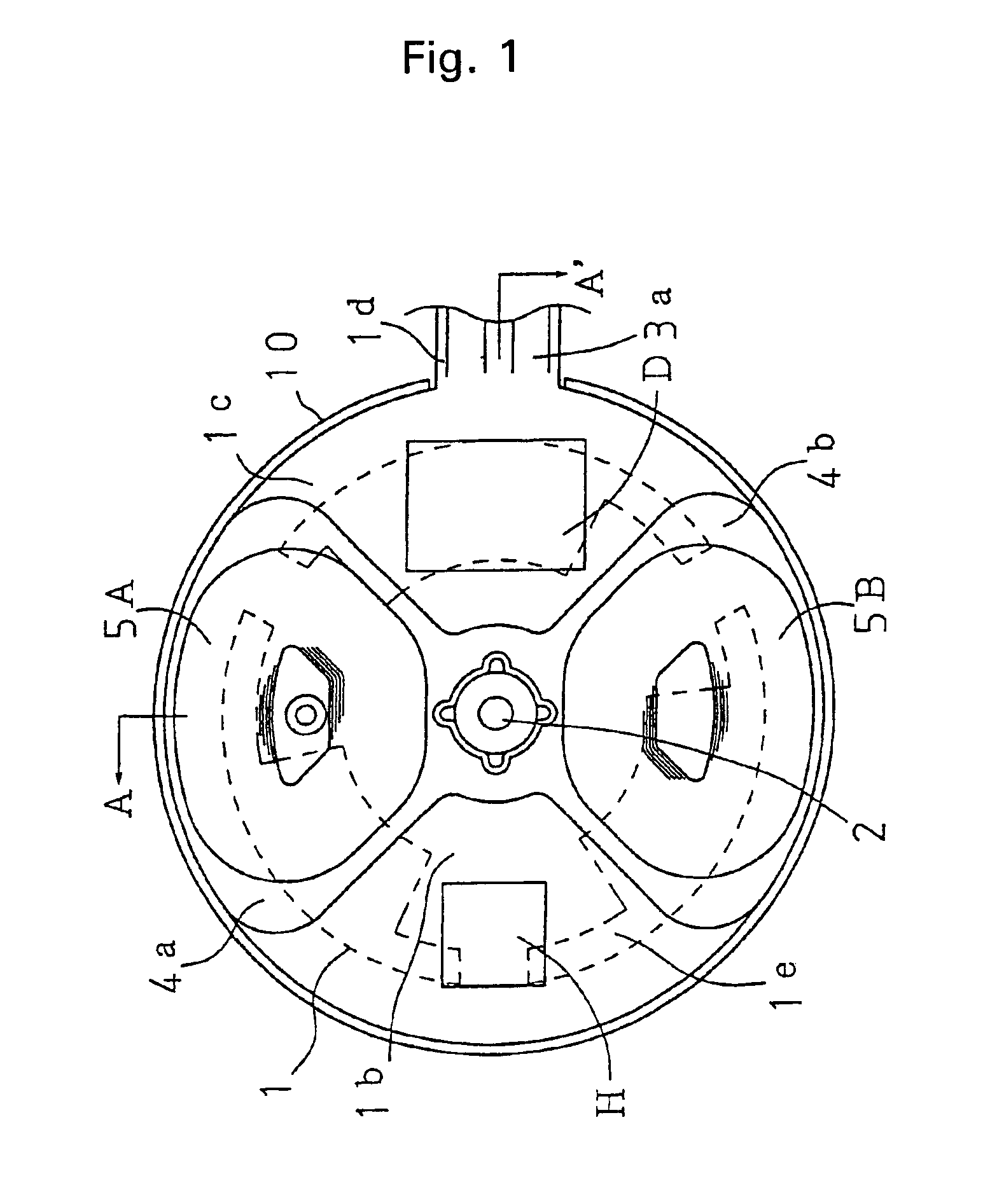
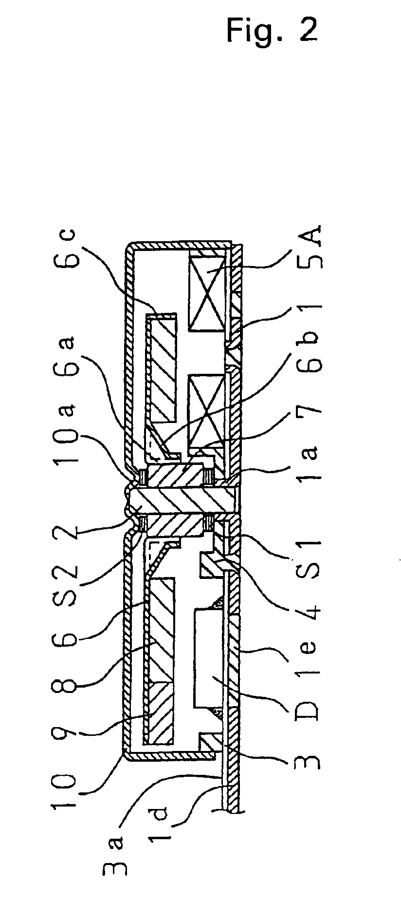
[0037]An axial-air-gap brushless vibration motor of a coreless slotless system and a fixed shaft type in accordance with the present invention is shown in FIG. 1 and FIG. 2.

[0038]A yoke bracket 1 is composed of a thin stainless steel sheet with magnetic properties weaker that those of an iron sheet and a thickness of about 0.15 mm and has a shaft support portion 1a in the form of a ring in a center thereof and three detent torque generation portions 1b provided so as to extend with an angular spacing of about 120 degrees in the radial direction, as shown by a broken line in the figures.

[0039]Furthermore, in the yoke bracket 1, the detent torque generation portions 1b partially extend in the radial direction and a ring-shaped holding portion 1c also serving as a reinforcement is provided so as to close the three detent torque generation portions 1b.

[0040]Part of this holding portion 1c further protrudes in the radial direction and serves as a power feed terminal installation portion...

embodiment 2

[0056]A configuration representing a modification example of the yoke bracket as a stator member will be described below with reference to FIG. 3.

[0057]Components identical to those of the above-described embodiment or almost identical components having the same function as those of the above-described embodiment will be assigned hereinbelow with the same symbols and the explanation thereof will be omitted.

[0058]Thus, a specific feature of the yoke bracket 1 of this embodiment, which differentiates it from the yoke bracket of Embodiment 1, is that the width of the detent torque generation portions 1b is almost equal to that of the neutral zone of the magnetic pole of the below-described axial-air-gap magnet which is to be assembled.

[0059]Here, the shaft support portion 1a is formed to have a diameter less than the inner diameter of the magnet 8 which is to be assembled, and the inner diameter of the holding portion 1c is larger than the outer diameter of magnet 8. With such a config...

embodiment 3

[0062]FIG. 4 illustrates another embodiment of the yoke bracket. FIG. 5 illustrates the configuration of a stator equipped with this yoke bracket. Here, too, the components identical to those of the above-described embodiments, are assigned with the same reference symbols and explanation thereof is omitted.

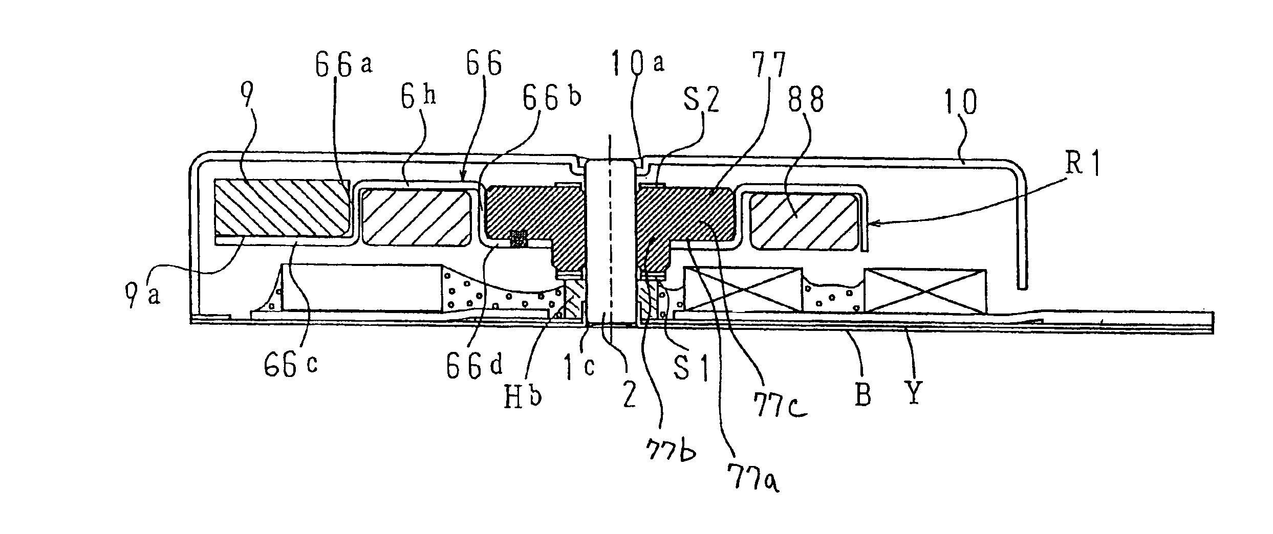
[0063]The yoke bracket YB comprises a yoke sheet Y composed of a thin sheet of a magnetic stainless steel or Permalloy with a thickness of 0.05 mm to 0.1 mm, and a bracket sheet B made from a nonmagnetic stainless steel or an elastic copper-nickel alloy attached, for example, by multiple spot welding L to the yoke sheet Y.

[0064]In the center of the bracket sheet B, the shaft support portion 1a is raised in the form of a bar ring, and a cylindrical reinforcing member Hb fabricated from a free-cutting bronze is press fitted therein so as to hold down the bar ring portion of the shaft support portion 1a.

[0065]The bracket sheet B is formed so that the contour thereof almost matches t...


PUM


Abstract

An axial-air-gap brushless vibration motor has an eccentric rotor R in which an axial-air-gap magnet and an arched weight are provided in a rotor yoke which is rotatably mounted on a shaft fixed to a yoke bracket. A stator base is attached to the yoke bracket which includes a magnetic portion receiving the magnetic field of the magnet and a nonmagnetic portion. One Hall sensor and a drive circuit member for receiving output of the Hall sensor are disposed so that they do not overlap on a radial plane, of the stator base which has single-phase air-core armature coils installed. A cover member is welded to the yoke bracket.

Description

BACKGROUND OF THE INVENTION[0001]1. Field of the Invention[0002]The present invention relates to an axial-air-gap brushless vibration motor suitable for silent information means for mobile communication devices, in particular, to an axial-air-gap brushless vibration motor containing a drive circuit.[0003]2. Description of the Related Art[0004]The Applicant has previously suggested a flat axial-air-gap brushless vibration motor of a coreless and slotless type, this motor containing no drive circuit component (Japanese Utility Model Application Laid-open No. H4-137463 and Japanese Patent Application Laid-open No. 2002-143767).[0005]A cored motor of a non-circular configuration in which armature coils are wound on a plurality of equidistantly disposed protruding poles and a drive circuit component is disposed on a side of a stator is known as a brushless vibration motor equipped with a drive circuit (Japanese Patent Application Laid-open No. 2000-245103).[0006]However, a width of such ...

Claims


Application Information

Patent Timeline
Patent Type & Authority Patents(United States)
IPC IPC(8): H02K7/06H02K11/04H02K29/00
CPCH02K7/063H02K11/0073H02K2211/03H02K11/33
Inventor YAMAGUCHI, TADAOYASHIMA, TETUSHITAKAGI, MASAHIROSHIMOSEGAWA, SATORUFUJII, KENTARO
Owner TOKYO PARTS IND CO LTD
Why Eureka
Try Eureka