Airport safety system

a safety system and airfield technology, applied in the field of airport safety systems, can solve the problems of increasing the time the aircraft occupies the main runway, the aircraft may slow down excessively, and the potential danger of landing, so as to achieve the effect of further enhancing the use of the system

Inactive Publication Date: 2009-05-19
CORRIGAN NIGEL
View PDF25 Cites 6 Cited by
  • Summary
  • Abstract
  • Description
  • Claims
  • Application Information

AI Technical Summary

Benefits of technology

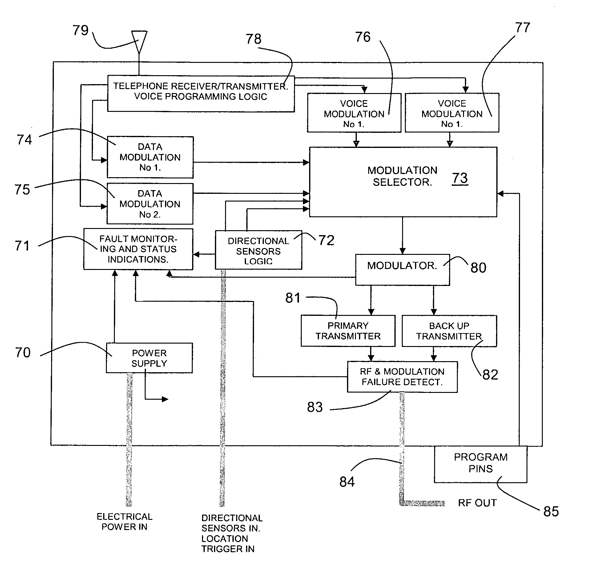
[0013]The use of pre-recorded voice messages also permits the system to inform an aircraft's pilot of the aircraft's current location and to warn of approaching junctions or other features to which the pilot may need to be alerted. Means may be provided for changing the messages according to changes in prevailing conditions. For example, closure of a taxiway or runway can be announced. The updating means may comprise a communication link, permitting Air Traffic Control (ATC) to change the message in a selected message transmitting device simply by communicating with the device and recording the new message. The communication link may be a wired link, but it could alternatively be a radio link, for example a cellular telephone link. The recording of the voice messages will be conveniently implemented digitally in solid state memory devices, to minimise maintenance required, although other recording and playback devices could be used.
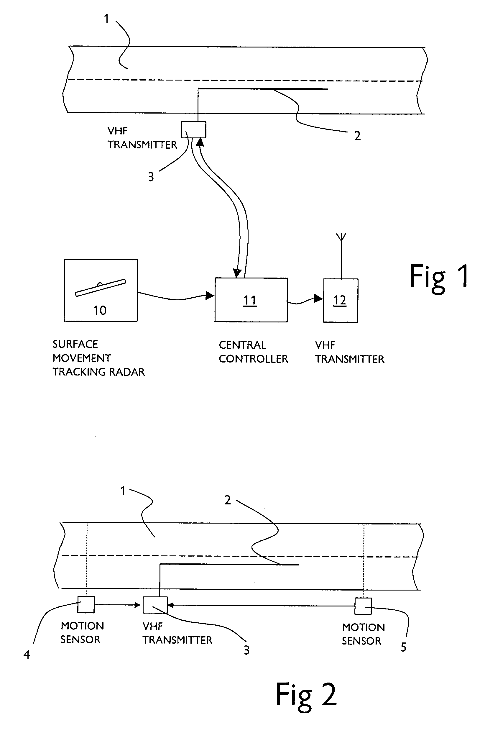
[0017]The usefulness of the system may be further enhanced by incorporating in the message transmitting device means for sensing the direction of motion of the aircraft. Such means could, for example, be connected to a pair of spaced inductive loops across the path of the aircraft, the sequence of signals from the two loops being used to provide the indication of direction. According to the direction sensed, one of two different pre-recorded messages may be transmitted to the aircraft. It will be understood that other motion sensing devices could be used as an alternative.

Problems solved by technology

Complex and unfamiliar airport layouts and / or low visibility conditions can lead to pilots mistakenly taking a wrong direction, leading to potentially dangerous situations, for example a taxiing aircraft turning on to a runway in the path of another aircraft taking off or landing, or an aircraft attempting to take off from the wrong runway, perhaps one obstructed by repair works or other aircraft.
A less dangerous consequence of unfamiliarity with ground layout, but one with potentially significant economic effects, is that landing aircraft may slow down excessively after touch down to enable the pilot to locate his turn off to the taxiway.
This increases the time the aircraft occupies the main runway, delaying its availability for the next landing.
Further, while the gradual phasing out of ILS marker beacons in favour of more sophisticated navigational systems is beginning to take place, it will be some considerable time before the airborne equipment is no longer required.
While this system might enable the pilot to avoid confusion between a taxiway and a runway, for example, it cannot provide any clear guidance as to whether the pilot is heading in the correct direction on the correct taxiway or runway.
The success of these predictive systems has been less than hoped for, due mainly to the difficulties in determining the points at which normal traffic separation deteriorates to become a hazard.
Too broad a decision window and false alarms are too frequent; too narrow a decision window and alerts to the controller leave no time to rectify the situation.

Method used


Image

  • Airport safety system
  • Airport safety system
  • Airport safety system

Examples


Embodiment Construction

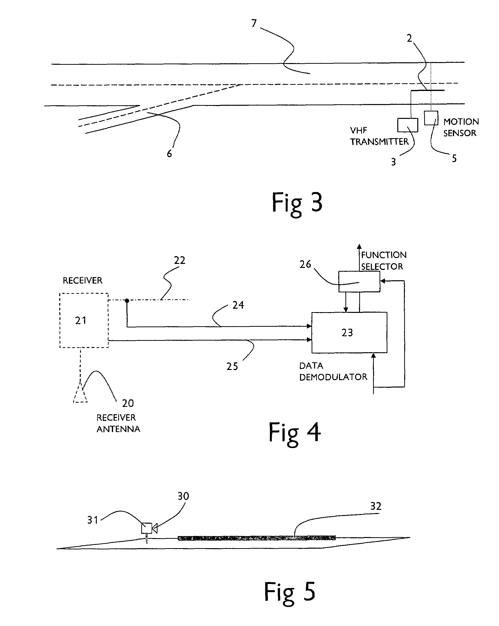
[0028]Referring first to FIG. 1, an airport runway or taxiway 1 has embedded in the surface thereof a radio antenna in the form of a radiating cable 2 fed with a 75 MHz signal from a message transmitting device 3, conveniently located alongside the runway or taxiway and provided with electrical power from the edge lighting system present in most runways and taxiways. The 75 MHz carrier signal from the transmitter is modulated (amplitude modulation, in accordance with standard practice) with a pre-recorded voice message giving positional information, for example “Taxiway Golf, Northbound Delta, Southbound Bravo”. The transmitter may simply be arranged to operate passively, in other words repeating the message at regular intervals regardless of the presence or absence of an aircraft in the vicinity, but is preferably provided with means for detecting the presence of an aircraft within range of the signal radiated by the antenna to cause activation of the transmitter. The detecting mea...


PUM


Abstract

An airport safety system is disclosed, comprising surface movement radar for monitoring the movement of aircraft and land vehicles on an airport, said surface movement radar providing a signal input to a computer arranged to identify from the relative motions of aircraft and vehicles detected by the radar in accordance with a pre-programmed set of rules an aircraft at risk of collision. The computer is also programmed to cause transmission by radio of an audible alert signal when a risk is predicted, said radio transmission being at a standard aircraft communication frequency, such as the standard ground communication VHF radio channel. The alert signal can alternatively be transmitted by one of a plurality of message transmitting devices arranged at different locations adjacent to airport runways and taxiways, each message transmitting device comprising a radio transmitter connected to antenna means arranged to radiate a signal within a predetermined area at the location. The radio transmitters operate at standard Marker beacon frequency amplitude modulated by said alert signal. The computer is programmed to identify the transmitting device adjacent to said aircraft at risk of collision and to direct said alert signal to the transmitting device so identified for transmission thereby. In this way, the alert signal could be directed to only the aircraft involved.

Description

[0001]This is a continuation-in-part application based upon U.S. patent application Ser. No. 10 / 148,066, filed May 24, 2002, now U.S. Pat. No. 6,947,742, which claims foreign priority to GB Application Serial Nos. 9927816.0 (filed Nov. 25, 1999); 0021571.5 (filed Sep. 4, 2000); and 0428502.9 (filed Dec. 30, 2004).FIELD OF THE INVENTION[0002]This invention relates to an airport safety system for providing audible warning messages to aircraft of the risk of collision on or near the ground.BACKGROUND TO THE INVENTION[0003]During ground operations, i.e. taxiing, aircraft pilots rely solely on charts, taxiway markings and illuminated marker boards to determine their current location and the direction to their next position. Complex and unfamiliar airport layouts and / or low visibility conditions can lead to pilots mistakenly taking a wrong direction, leading to potentially dangerous situations, for example a taxiing aircraft turning on to a runway in the path of another aircraft taking of...

Claims


Application Information

Patent Timeline
Patent Type & Authority Patents(United States)
IPC IPC(8): G01S13/93
CPCG08G5/0013G08G5/0082G08G5/065G01S2013/916
Inventor CORRIGAN, NIGEL
Owner CORRIGAN NIGEL
Why Eureka
Try Eureka