Working machine that can clamp a workpiece automatically

a workpiece clamping and workpiece technology, applied in the field of working machines, can solve the problems of user inconvenience and user danger, and achieve the effect of saving manual work, convenient operation and convenient use for users

Inactive Publication Date: 2009-05-26
CHANG PIN FENG
View PDF12 Cites 2 Cited by
  • Summary
  • Abstract
  • Description
  • Claims
  • Application Information

AI Technical Summary

Benefits of technology

[0007]The primary objective of the present invention is to provide a working machine that can clamp a workpiece automatically.
[0008]Another objective of the present invention is to provide a working machine, wherein the working machine is operated by a user's one foot so as to perform a drill working process on the workpiece, so that the working machine is operated easily and conveniently, thereby greatly facilitating the user operating the working machine, and thereby saving manual work.
[0009]A further objective of the present invention is to provide a working machine, wherein the workpiece is clamped automatically without having to hold the workpiece by a user's one hand, thereby protecting the user's safety during the working process.
[0010]A further objective of the present invention is to provide a working machine, wherein the workpiece is clamped and the working process is performed simultaneously, so that the working machine is operated rapidly, thereby greatly saving the working time.

Problems solved by technology

However, the user has to hold the workpiece by his one hand and to operate the drive unit 14 by his other hand, thereby causing inconvenience to the user.
In addition, the user has to hold the workpiece by his one hand so that the working tool 131 of the working mechanism 13 easily hurts the user's one hand, thereby causing danger to the user.

Method used


Image

  • Working machine that can clamp a workpiece automatically
  • Working machine that can clamp a workpiece automatically
  • Working machine that can clamp a workpiece automatically

Examples


Embodiment Construction

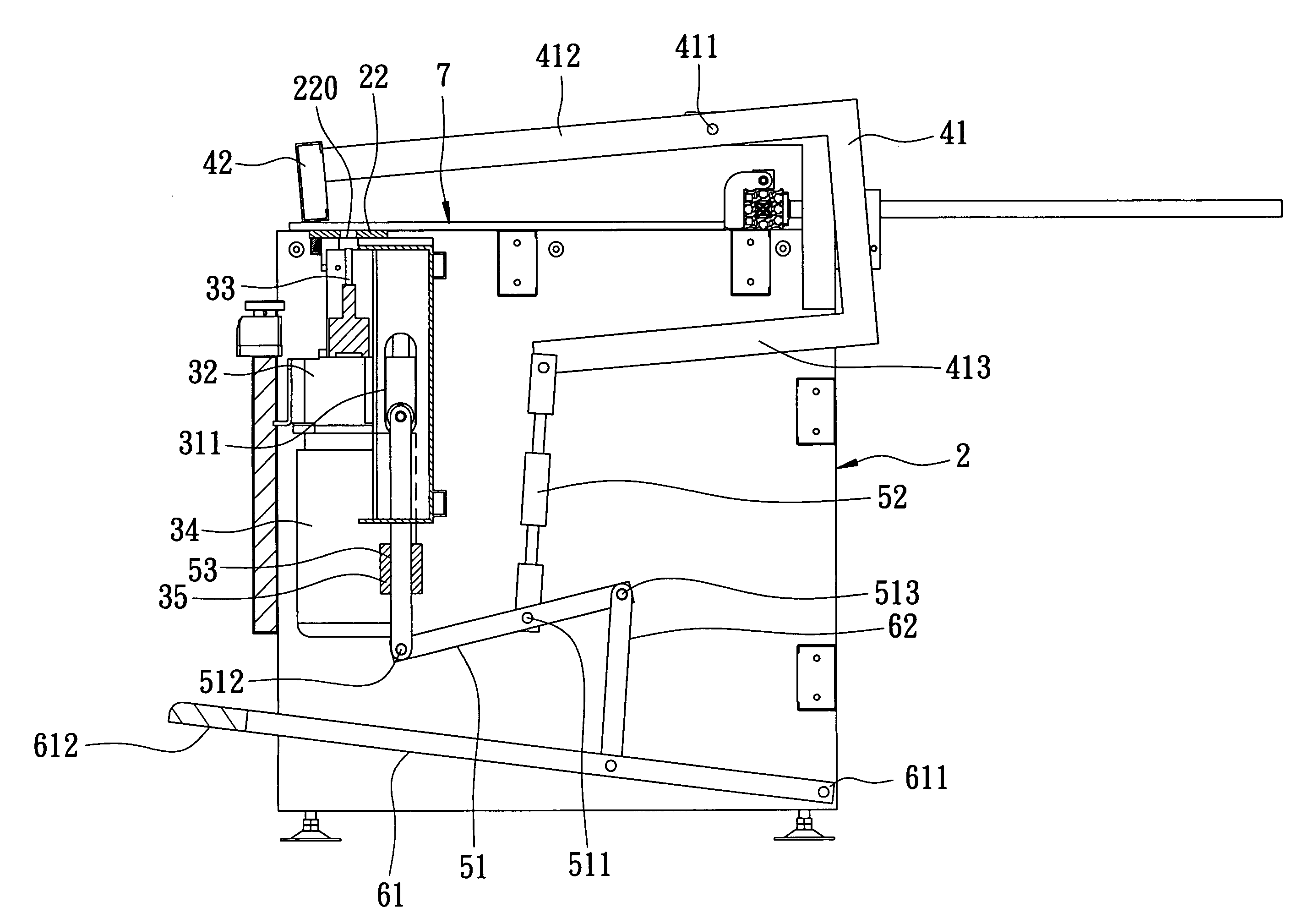
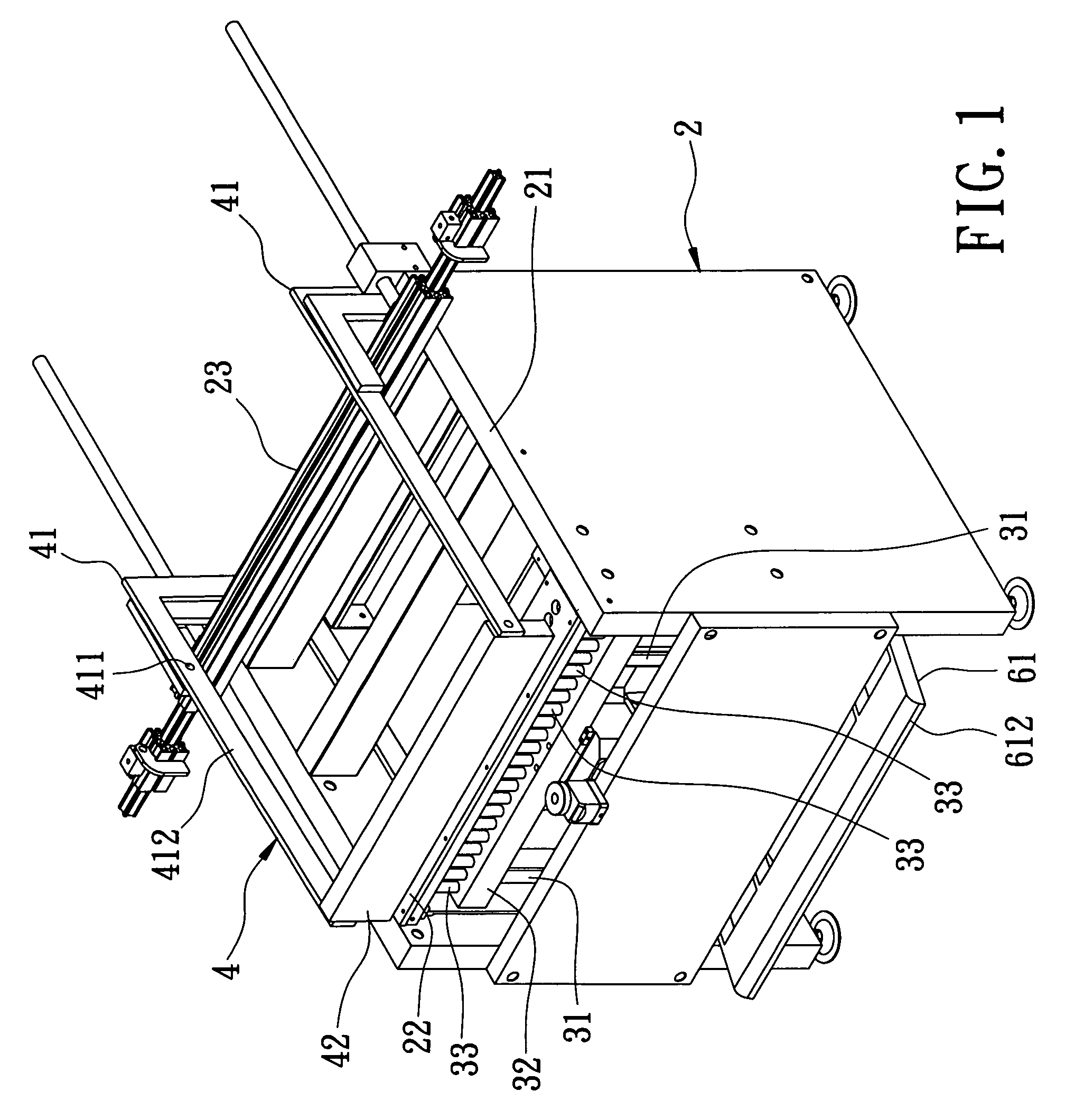
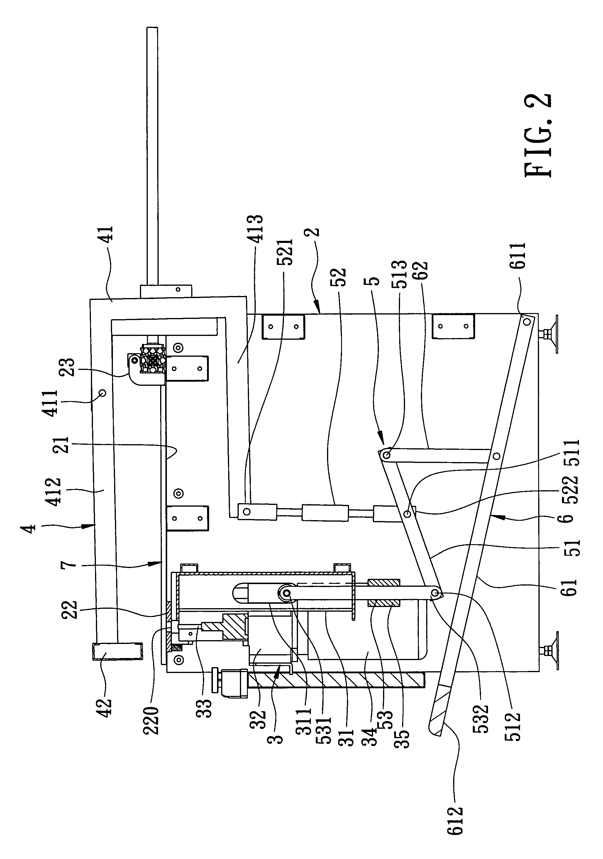
[0019]Referring to the drawings and initially to FIGS. 1 and 2, a working machine in accordance with the preferred embodiment of the present invention comprises a base 2, a working mechanism 3, a clamping unit 4, a linkage 5, and a drive unit 6.

[0020]The base 3 has a top face 21 provided with a work table 22 for placing a workpiece 7, such as a wood material, and a limit unit 23 is movably mounted on the top face 21 of the base 2 and movable relative to the work table 22.

[0021]The working mechanism 3 is mounted on the base 2 and includes two tracks 31 secured in the base 2 and extended in a perpendicular direction, a slide 32 movably mounted on the tracks 31, at least one working tool 33 mounted on the slide 32 to move therewith and located opposite to the work table 22, at least one motor 34 mounted on the slide 32 to drive the working tool 33, and a counterweight 35 secured on the slide 32. Each of the tracks 31 has an axially extending elongated slot 311. The counterweight 35 has...


PUM

PropertyMeasurementUnit
weightaaaaaaaaaa
timeaaaaaaaaaa
movementaaaaaaaaaa

Abstract

A working machine includes a base for placing a workpiece, a working mechanism movable relative to a first face of the workpiece, a clamping unit movable relative to a second face of the workpiece, a linkage connected to the working mechanism and the clamping unit to drive the working mechanism and the clamping unit to move relative to the workpiece simultaneously, and a drive unit connected to the linkage. Thus, the working machine is operated by a user's one foot, so that the working machine is operated easily and conveniently. In addition, the workpiece is clamped automatically without having to hold the workpiece by a user's one hand, thereby protecting the user's safety.

Description

BACKGROUND OF THE INVENTION[0001]1. Field of the Invention[0002]The present invention relates to a working machine, and, more particularly, to a working machine, such as a drilling machine for working a workpiece, such as a wood material.[0003]2. Description of the Related Art[0004]A conventional working machine 1 in accordance with the prior art shown in FIG. 7 is used for working a workpiece (not shown), such as a wood material and comprises a work table 11 for placing the workpiece, a limit unit 12 movably mounted on the work table 11 to retain the workpiece, a working mechanism 13 movably mounted on the work table 11 and movable relative to the workpiece, and a drive unit 14 mounted on the work table 11 to drive the working mechanism 13 to move relative to the work table 11 and the workpiece. The working mechanism 13 includes a working tool 131, such as a drill tip, and a motor 132 for driving the working tool 131. In operation, the working mechanism 13 is driven by the drive un...

Claims


Application Information

Patent Timeline
Patent Type & Authority Patents(United States)
IPC IPC(8): B23B47/18
CPCB23B47/00B23Q3/06B27C3/06B27C3/00Y10T408/563Y10T408/6786
Inventor CHANG, PIN-FENG
Owner CHANG PIN FENG
Why Eureka
Try Eureka