
System and method for managing power consumption

a power consumption and system technology, applied in the direction of liquid/fluent solid measurement, sustainable buildings, instruments, etc., can solve the problems of wasteful and inappropriate worst-case scenarios, waste of safe minimum power level, and inability to meet the needs of electronic components, etc., to achieve the effect of optimizing power consumption and conserving power in an electronic devi

Inactive Publication Date: 2009-05-26
BROADCOM INT PTE LTD
View PDF3 Cites 22 Cited by
  • Summary
  • Abstract
  • Description
  • Claims
  • Application Information

AI Technical Summary

Benefits of technology

"The invention is about an electronic circuit that has built-in self-testing capabilities to optimize power consumption. The circuit includes a component circuit that operates at an optimal power level, a power supply that provides power to the component circuit, and a test circuit that monitors the power supplied to the component circuit and controls the power supply. The test circuit reduces the power supplied to the component circuit until it is operating at the optimal level. This allows for individual optimization of power consumption for each component in an electronic device. The test circuit can also anticipate operating modes and events to further conserve power. Once the optimal power levels are known, the power levels can be set for future operating conditions, modes, and circumstances."

Problems solved by technology

However, conventional devices are often limited by the number and capacity of these functions by the amount of battery power available.
As such, electronic components' power consumption is a key factor considered when designing electronic devices.
If is often the case, however, that the worst-case scenario set at a safe minimum power level may be wasteful and inappropriate for some situations and components.
Thus, power is wasted because the power supply is set to a specific worst-case level in order to ensure proper operation of all components in the device when there may be additional “head-room” for lowering the supplied power levels on a component by component basis.
Furthermore, this type of power management cannot react to a real-time change in operating variables, such as temperature and battery life remaining.

Method used


Image

  • System and method for managing power consumption
  • System and method for managing power consumption
  • System and method for managing power consumption

Examples


Embodiment Construction

[0012]The following discussion is presented to enable a person skilled in the art to make and use the invention. The general principles described herein may be applied to embodiments and applications other than those detailed above without departing from the spirit and scope of the present invention. The present invention is not intended to be limited to the embodiments shown, but is to be accorded the widest scope consistent with the principles and features disclosed or suggested herein.

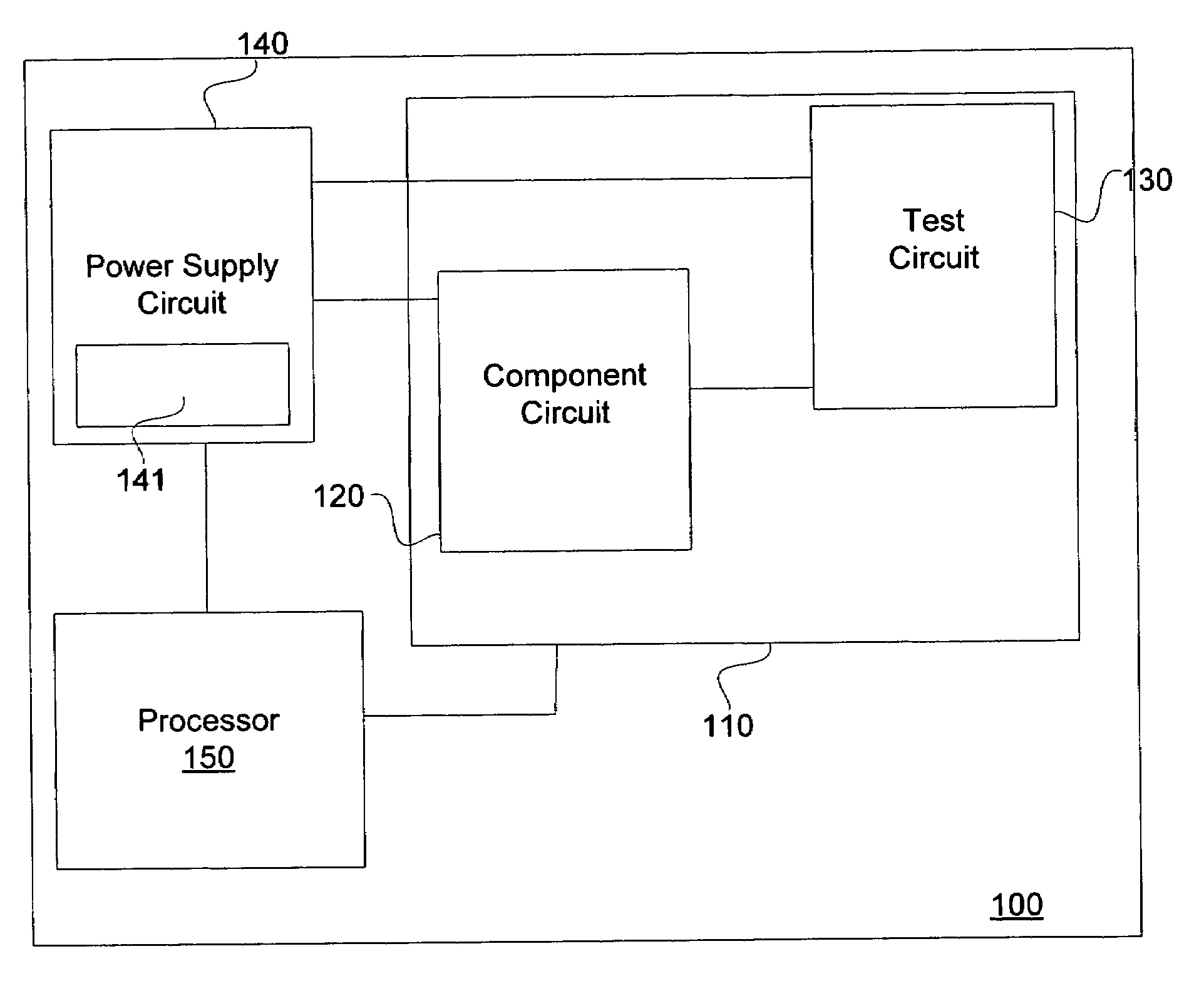
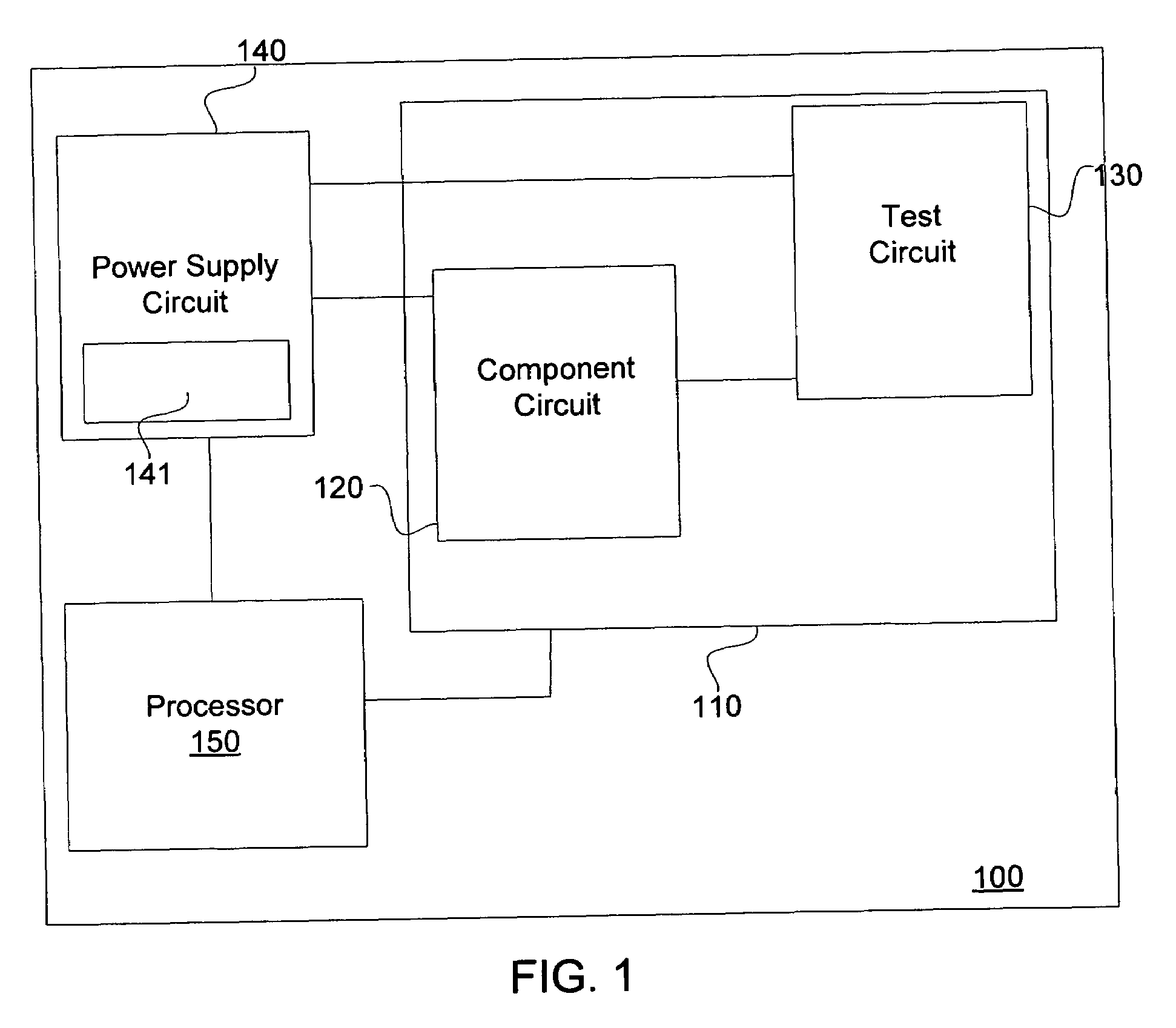
[0013]FIG. 1 is a functional block diagram generally illustrating an electronic device having power conservation capabilities according to an embodiment of the invention. The electronic device 100 is generally representative of an operating environment that may be implemented in any number of electronic systems including handheld devices, digital cameras, digital video cameras, and the like. Although described in some examples to follow in the context of a digital imaging device, it is appreciated t...


PUM


Abstract

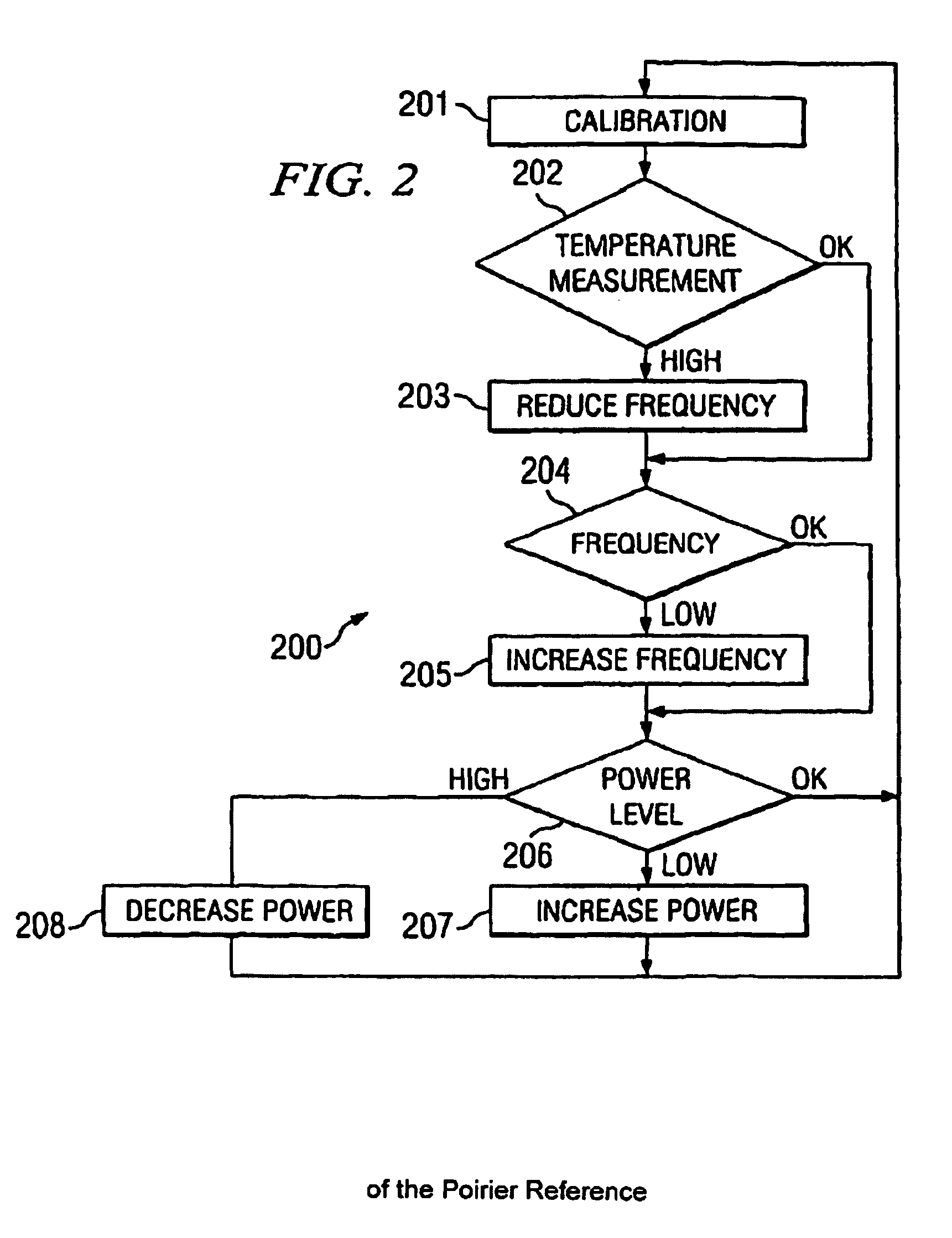
An electronic circuit having built-in self testing capabilities for optimizing power consumption. Typically, the electronic circuit includes a component circuit that operates at some known or unknown optimal operating power level. Further, the electronic circuit includes a power supply coupled to the component circuit such that the power supply provides power to the component circuit. Further yet, the electronic circuit includes a test circuit coupled to the component circuit and coupled to the power supply. The test circuit is operable to monitor the power supplied to the component circuit and operable to control the power supply. In an iterative manner, the test circuit reduces the power supplied to the component circuit until the power supplied to the component circuit is operating at the optimal operating power level.

Description

BACKGROUND OF THE INVENTION[0001]Integrated Circuits (ICs) and Electronic Circuit Boards (ECBs) are prevalent in today's electronics as they are becoming more functional and easier and cheaper to manufacture. Portable devices employing ICs and ECBs are capable of performing many functions based solely on power supplied by a battery. However, conventional devices are often limited by the number and capacity of these functions by the amount of battery power available. As such, electronic components' power consumption is a key factor considered when designing electronic devices.[0002]Typically, electronic circuits in these devices are designed with a “worst-case scenario” in mind. That is, the amount of power (i.e., current and / or voltage) supplied to each component in the device is set to a level that assures correct operation. If is often the case, however, that the worst-case scenario set at a safe minimum power level may be wasteful and inappropriate for some situations and compone...

Claims


Application Information

Patent Timeline
Patent Type & Authority Patents(United States)
IPC IPC(8): G06F1/32
CPCG06F1/3203G06F1/3296Y02B60/1285Y02D10/00
Inventor MENTZER, RAY A.BECK, JEFFREY S.
Owner BROADCOM INT PTE LTD
Learn More