
All-digital phase-locked loop built-in self-testing structure

An all-digital phase-locked loop, built-in self-test technology, applied in the direction of automatic power control, electrical components, etc., to achieve high fault coverage, extended test time, and low cost.

Inactive Publication Date: 2014-08-13
SOUTHEAST UNIV
View PDF3 Cites 12 Cited by
  • Summary
  • Abstract
  • Description
  • Claims
  • Application Information

AI Technical Summary

Problems solved by technology

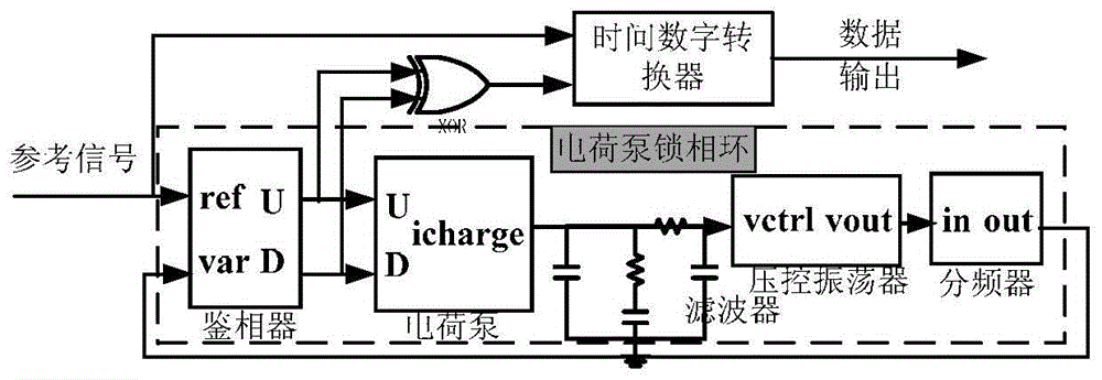
PLL is the only mixed-signal circuit on most SoCs. Its test time and test cost are directly converted to the production cost of electronic products, and its test accuracy may also affect the performance of the entire electronic product. Therefore, the three must be coordinated

Method used


Image

  • All-digital phase-locked loop built-in self-testing structure
  • All-digital phase-locked loop built-in self-testing structure
  • All-digital phase-locked loop built-in self-testing structure

Examples


Embodiment Construction

[0030] The present invention will be further described below in conjunction with the accompanying drawings.

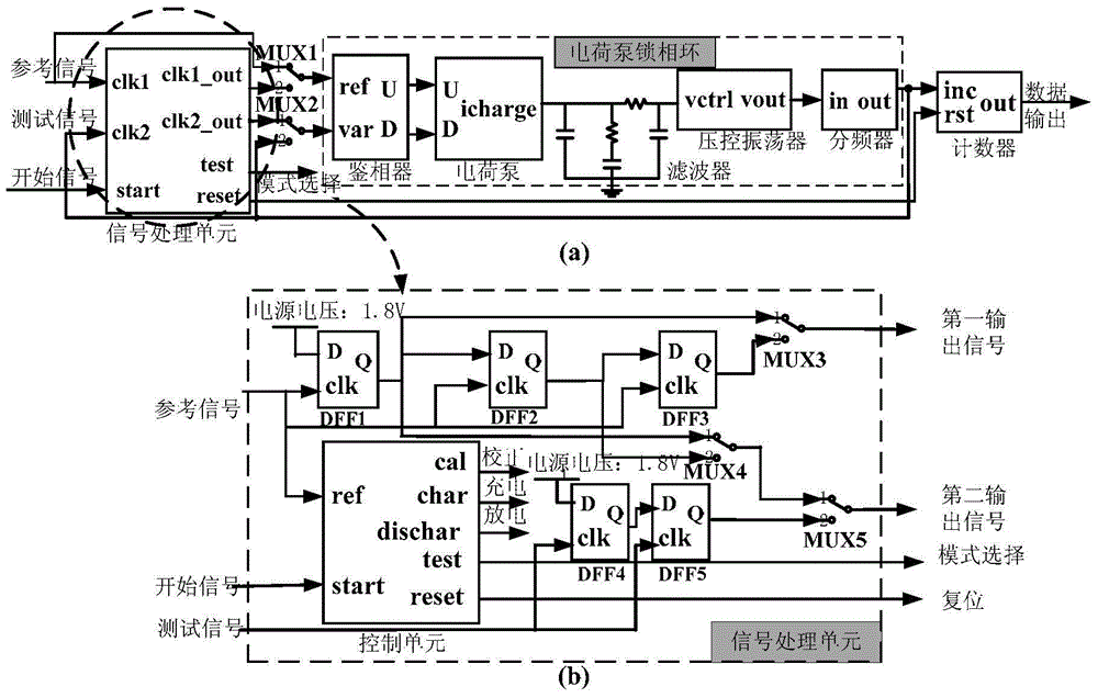
[0031] As shown in Figure 1(b), it is a built-in self-test structure of an all-digital phase-locked loop, which converts the time difference between the reference signal and the test signal into a digital signal output, including a signal processing unit, a first two-way switch MUX1, The second two-way switch MUX2, the phase-locked loop to be tested and the counter, the phase-locked loop to be tested is a charge pump phase-locked loop; the reference signal and the test signal are respectively connected through the first two-way switch MUX1 and the second two-way switch MUX2 At the input terminal of the phase-locked loop to be tested, the phase-locked loop to be tested converts the time difference △T of the two input signals into a frequency change △f, and then records the number of pulses through the counter, and converts the frequency change △f into the change of the c...


PUM


Abstract

The invention discloses an all-digital phase-locked loop built-in self-testing structure. The time difference between a reference signal and a test signal is converted into a digital signal to be output. The all-digital phase-locked loop built-in self-testing structure comprises a signal processing unit, a first dual-path switch MUX1, a second dual-path switch MUX2, a phase-locked loop to be tested and a counter. The phase-locked loop to be tested is a charge pump phase-locked loop. The reference signal and the test signal are connected to the input end of the phase-locked loop to be tested through the first dual-path switch MUX1 and the second dual-path switch MUX2 respectively, the time difference delta T of two input signals is converted into frequency variation delta f through the phase-locked loop to be tested, then the number of pulses is counted through the counter, and the frequency variation delta f is converted into count value variation delta N. The all-digital phase-locked loop built-in self-testing structure has the advantages of being fully digital, high in precision and low in cost.

Description

technical field [0001] The invention relates to a novel all-digital phase-locked loop built-in self-test structure, which can simultaneously complete the fault test and jitter test of the phase-locked loop. Background technique [0002] The testing of mixed-signal circuits has a great impact on the time-to-market and production costs of electronic products, and it is a major problem that needs to be solved urgently for the continued development of mixed-signal integrated circuits. Phase-locked loops as mixed-signal modules are widely used in frequency synthesis, phase demodulation, clock distribution, and time recovery, and are an essential part of wireless communications, optical fiber links, and microcomputers. However, due to the closed-loop feedback and mixed-signal characteristics of the phase-locked loop, it becomes one of the most difficult circuits to test, and its testing has become an urgent problem to be solved internationally. Therefore, the research on the built...

Claims


Application Information

Patent Timeline
IPC IPC(8): H03L7/08
Inventor 吴建辉閤兰花黄成李红陈超田茜
Owner SOUTHEAST UNIV
Learn More