
Method of and apparatus for detecting an error in writing to persistent memory

a persistent memory and error detection technology, applied in the direction of memory adressing/allocation/relocation, instruments, fault response, etc., can solve the problems of flash memory quickly wearout, memory will eventually wear out, and long tim

Inactive Publication Date: 2009-05-26
SHARP KK
View PDF16 Cites 3 Cited by
  • Summary
  • Abstract
  • Description
  • Claims
  • Application Information

AI Technical Summary

Benefits of technology

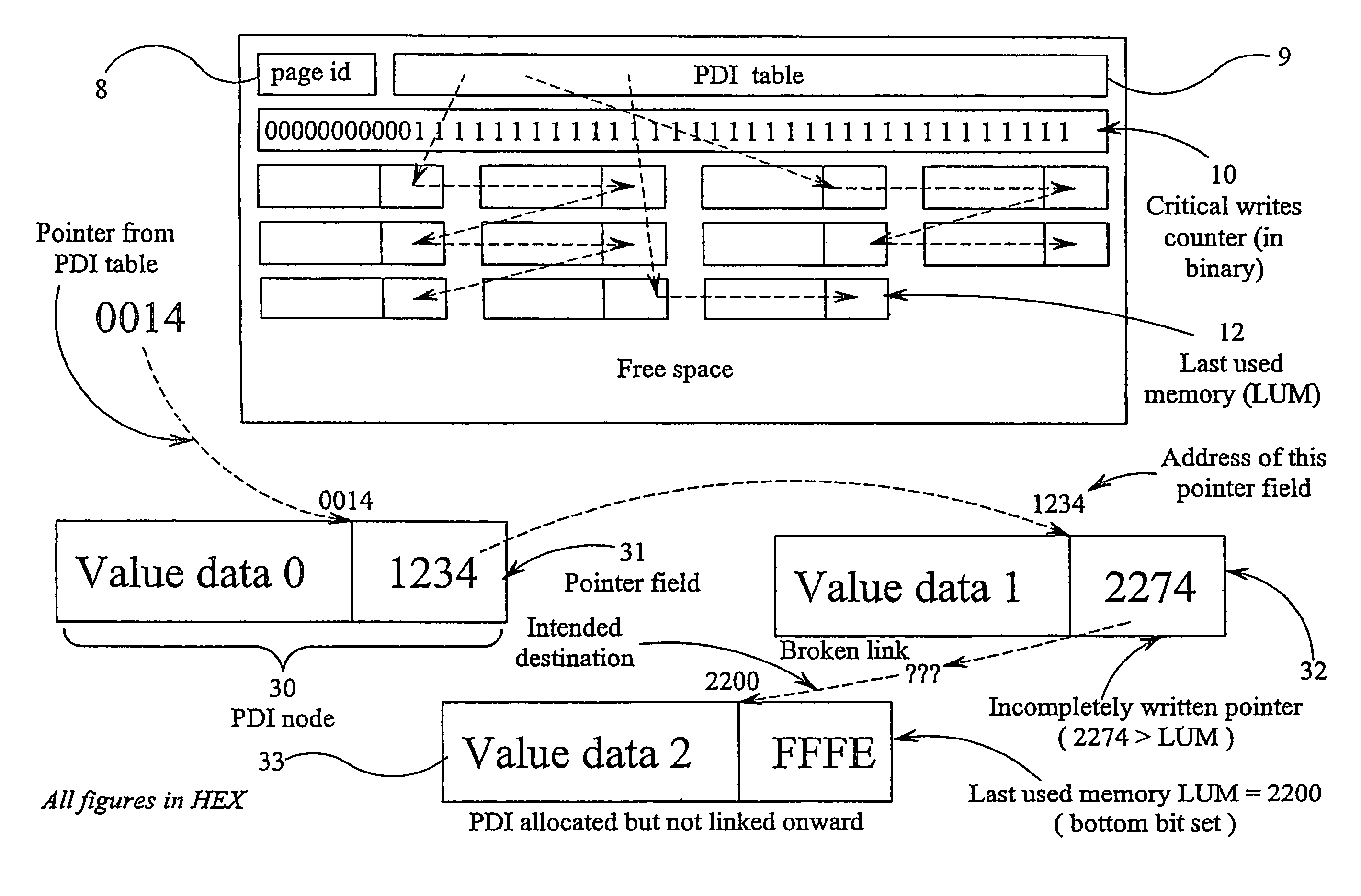
[0041]It is thus possible to provide an arrangement which allows errors in pointers of linked chains of PDIs and similar structures to be detected reliably. This technique also allows such errors to be corrected. Thus, for example, any application relying on PDIs stored in flash memory or the like is prevented from inadvertently using incorrect data read from the memory.

Problems solved by technology

Also, the memory will eventually wear out after some number of erase cycles (say 100,000 for high quality Flash).
If the date were stored in the same location each time it changes, the whole 64K block would first have to be erased because of the physical memory limitations and this would take a long time and rapidly wear out the flash memory.
It is assumed that this program has to share the flash memory with other programs, so it is not efficient to pre-allocate a large block of flash memory just for this one application.
If power is removed from a flash memory during a write cycle, there is a danger that the operation will be incomplete and that an inconsistent state will be available when power is reapplied.
When a write operation is interrupted by power loss, some or all of the requested changes from 1 to 0 may have occurred but it is impossible to identify which changes have occurred and which (if any) have not.
When power is applied again, the smart card cannot tell whether the stored data has been corrupted because of power loss during a write cycle.
If power fails when the pointer to the last value is being written into the flash memory, it may not be possible to retrieve the last value when power is restored.
Any application relying on such a last value will therefore not function correctly or may not function at all.

Method used


Image

  • Method of and apparatus for detecting an error in writing to persistent memory
  • Method of and apparatus for detecting an error in writing to persistent memory
  • Method of and apparatus for detecting an error in writing to persistent memory

Examples


Embodiment Construction

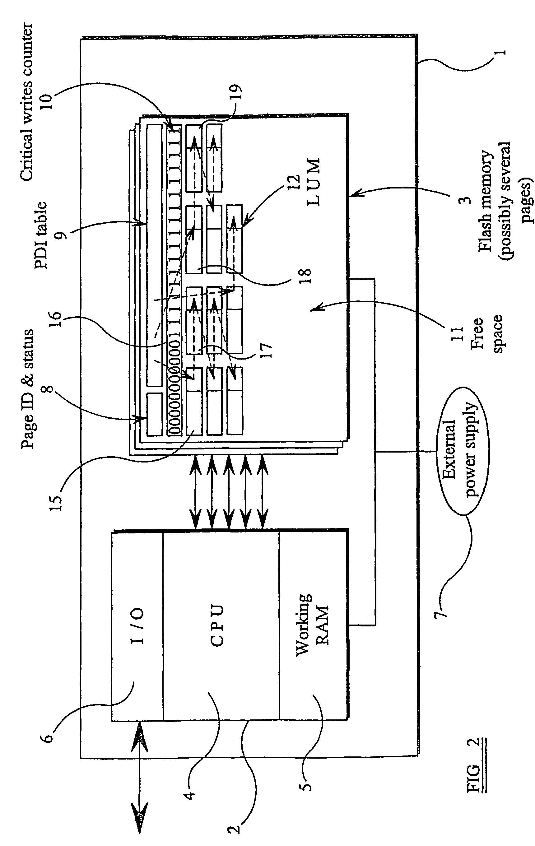
[0047]FIG. 2 illustrates a smart card of the “contactless” type for cooperating with a card reader to transfer data. The card 1 has embedded in it a computer 2 and a flash memory 3 shown as comprising several pages or segments. The computer 2 comprises a central processor unit (CPU) 4 provided with a working random access memory (RAM) 5 and an input / output interface (I / O) 6 for contactless communication with a card reader. The card 1 does not have an internal power supply but instead relies on an external power supply 7 provided within the card reader (not shown). The computer 2 and the memory 3 are thus only powered when the card 1 is correctly inserted in a card reader.

[0048]The flash memory segment illustrated in FIG. 2 is configured to act as a non-volatile memory for persistent data items (PDIs). Thus, whereas data which does not need to be stored in the absence of power uses the working RAM 5 which is volatile, PDIs whose values must be preserved in the absence of power are st...


PUM


Abstract

A technique is provided for detecting errors in persistent memory, such as flash memory, where values of data items are stored at memory locations added consecutively to one end of the already-allocated memory segment. When a new location is added, a pointer to the address of the new location is stored at the location of a preceding value for that item. The address of the latest location is determined (21) whenever power is reapplied. The pointer fields of the locations are searched (24) for any pointer whose value is greater than the address of the last location. If such a pointer value is found, this indicates that an error occurred when writing the pointer value, for example because power was removed before completion of the pointer writing cycle. The error can be corrected by changing the pointer value to the address of the last location (27).

Description

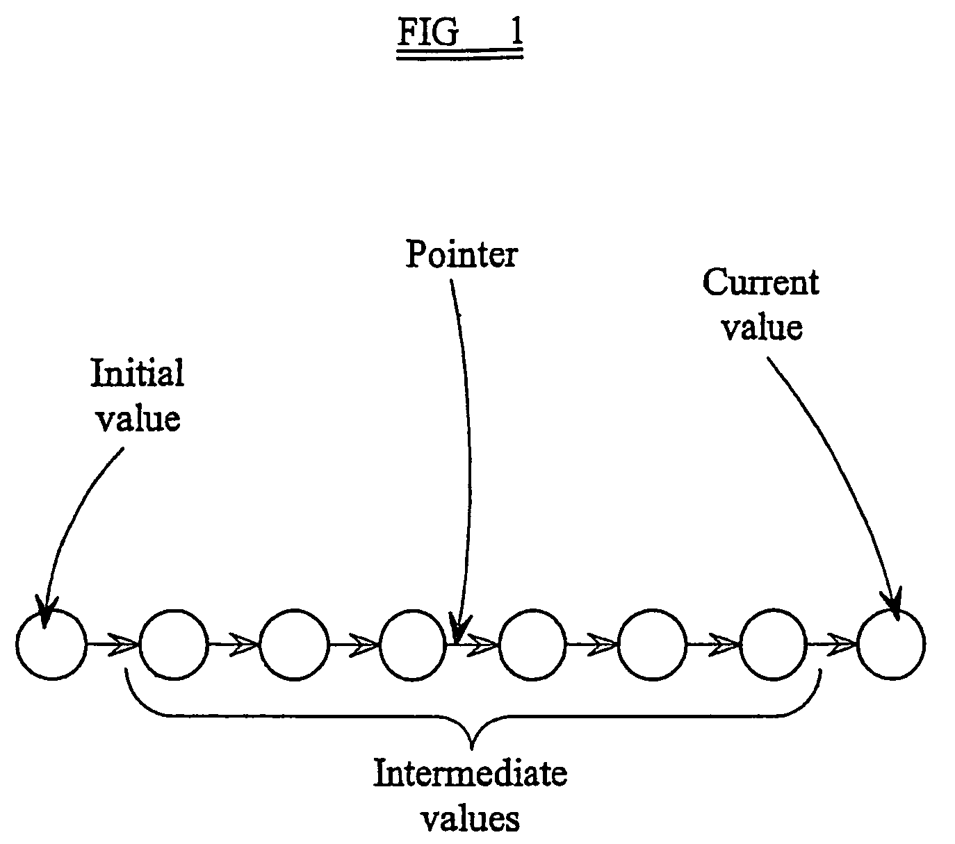
TECHNICAL FIELD[0001]The present invention relates to a method of and an apparatus for detecting an error in writing to persistent memory. The invention also relates to a method of and an apparatus for correcting the result of such an error. Such techniques may be used in embedded systems and examples of suitable applications include: smart cards such as Java Cards; digital active storage or security devices such as smart keys and smart disks; SIMs and USIMs for mobile telephones; data logging devices; small devices which record user preferences, store settings or log usage; computer systems in vehicles; set-top boxes; and internet routers. Such techniques are useful for persistent or “non-volatile” memories of the “write-once-erase-in-bulk” type, such as flash memory, and of the “write-only” type.BACKGROUND ART[0002]The term “Persistent Data Item” or “PDI” as used herein is defined to be a data item having associated with it a value which changes over time, in particular when updat...

Claims


Application Information

Patent Timeline
Patent Type & Authority Patents(United States)
IPC IPC(8): G01R31/28G06F3/06G06F11/00G06F11/07G06F11/10G06F12/02G06F17/30G11C16/10G11C16/34G11C29/00
CPCG06F3/0619G06F3/064G06F3/0679G06F11/073G06F11/0751
Inventor KAY, ANDREW
Owner SHARP KK
Learn More