Smart fuel control system

a fuel control system and intelligent technology, applied in the direction of engines, machines/engines, mechanical equipment, etc., can solve the problems of fuel system overheating, fuel overheating, and fuel overheating

Active Publication Date: 2009-06-02
HAMILTON SUNDSTRAND CORP
View PDF11 Cites 34 Cited by
  • Summary
  • Abstract
  • Description
  • Claims
  • Application Information

AI Technical Summary

Problems solved by technology

The pump is therefore oversize at operational rotational speed, so that it is three or four times larger than it need be for supplying fuel at operational rotational speed, thereby contributing to excess cost, size and weight of the fuel system.
Because the pump then develops excess flow at operational speed, the fuel recirculates through the pump by way of the pump relief valve, thereby contributing to unwanted heating of the fuel.

Method used


Image

  • Smart fuel control system
  • Smart fuel control system

Examples


Embodiment Construction

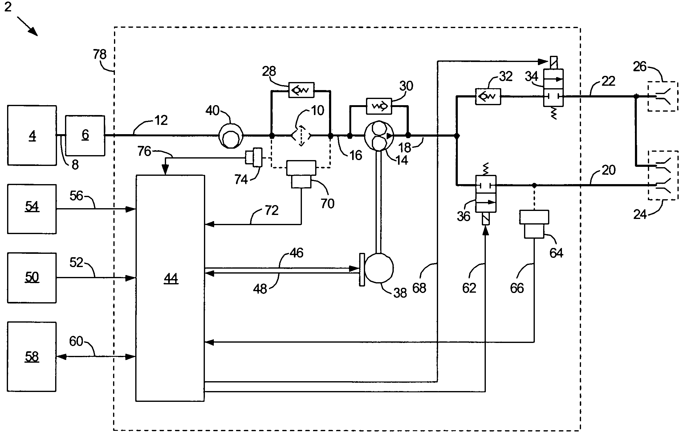
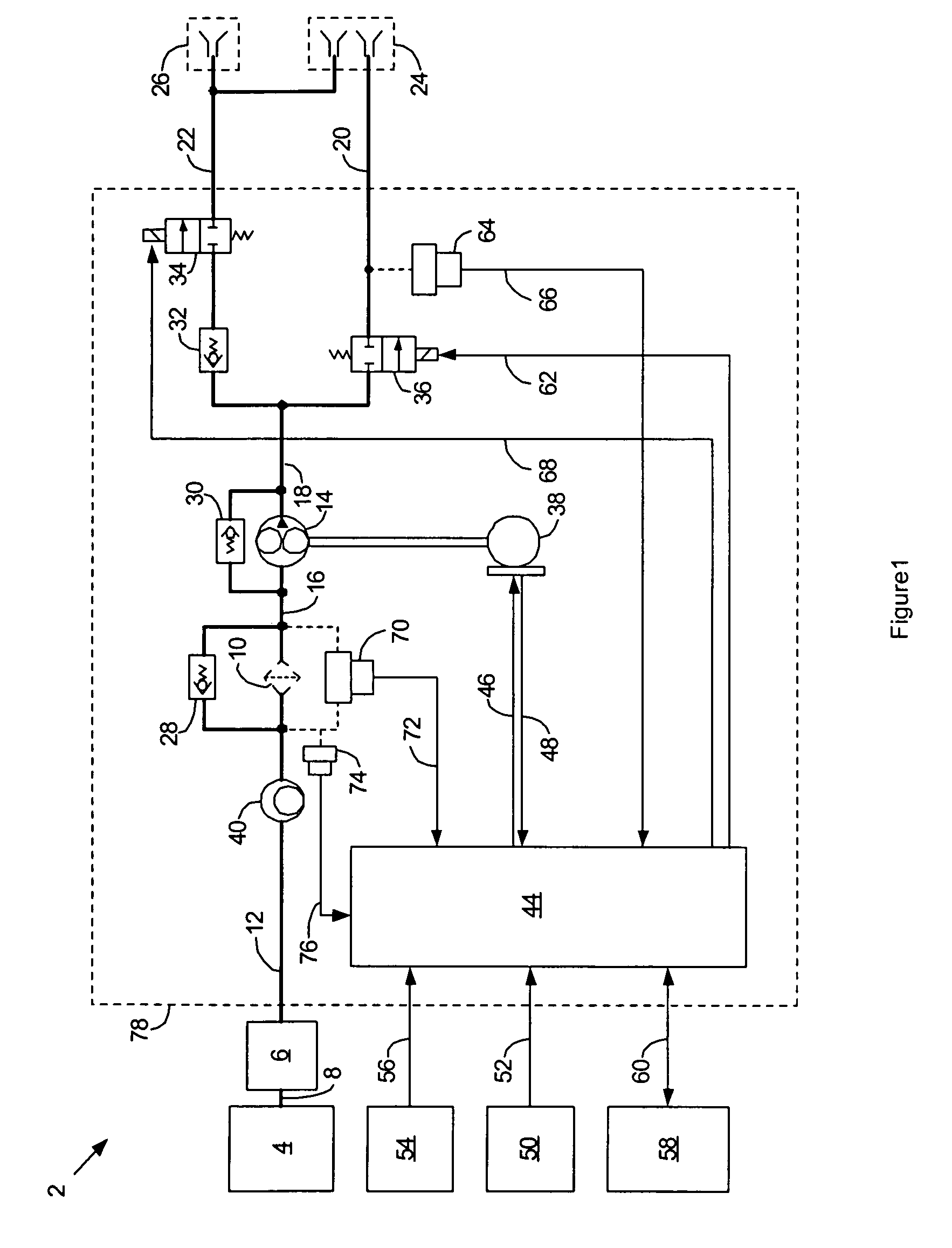
[0008]FIG. 1 is a schematic diagram of a fuel control system 2 for a gas turbine engine according to a possible embodiment of the invention. Fuel from a fuel supply source 4 feeds a spar valve 6 through a fuel supply line 8 for manual control of fuel flow. A fuel filter 10 filters fuel that passes through the spar valve 6 by way of a spar valve output line 12. A fuel pump 14, such as a gear pump, pumps fuel that passes through the filter 10 by way of a fuel filter output line 16. The fuel pump 14 supplies fuel through a pump supply line 18 to a start manifold 20 and a run manifold 22 for the engine. Typically, the start manifold 20 and run manifold 22 supply fuel to a plurality of duplex nozzles 24 and the run manifold 22 supplies fuel to a plurality of simplex nozzles 26. The nozzles 24 and 26 inject fuel into a combustor for the engine that ignites to provide engine power.

[0009]A fuel filter bypass valve 28 typically bypasses fuel around the fuel filter 10 in the instance that the...


PUM


Abstract

A fuel control system uses a fuel pump powered by a variable speed pump motor controlled by a closed loop electronic feedback system that tracks motor speed and corrects fuel pump motor speed so that the fuel pump delivers flow according to a desired flow schedule based on the pressure feedback from the manifold.

Description

FIELD OF THE INVENTION[0001]The invention relates to fuel systems for gas turbine engines, and more particularly to fuel control systems for gas turbine engines.BACKGROUND OF THE INVENTION[0002]Gas turbine engines generally have a fuel pump that transfers fuel from a fuel supply to the engine at a desired pressure and flow rate. The engine typically drives the fuel pump through a speed-reducing gearbox that couples the engine to the pump. Since the rotational speed of the pump, and therefore flow rate, is proportional to the rotational speed of the engine, it is common to use a servo-control valve to control fuel flow and a pump relief valve or pressure-regulating valve to control fuel pressure.[0003]The gearbox driven fuel pump has several disadvantages. One is that the size of the pump has to be sufficient to provide a large quantity of fuel to the engine during start-up of the engine, wherein the light-off window is only in the range of 5 to 15 percent of normal engine operationa...

Claims


Application Information

Patent Timeline
Patent Type & Authority Patents(United States)
IPC IPC(8): F02C9/00F02G3/00
CPCF02C7/22F02C9/28F02C9/30F05D2270/301
Inventor GOLDBERG, GARY L.FRANCISCO, JAY M.
Owner HAMILTON SUNDSTRAND CORP
Why Eureka
Try Eureka