
Apparatus for electromagnetic forming with durability and efficiency enhancements

a technology of electromagnetic forming and durability enhancement, which is applied in the direction of forging press details, manufacturing tools, forging presses, etc., can solve the problems of limited em forming applications to production, workpieces still hold a significant amount, and accelerate workpieces into die cavities, so as to reduce residual stresses in workpieces, optimize workpiece formability, and minimize long-term coil degradation.

Inactive Publication Date: 2009-06-02
FORD GLOBAL TECH LLC
View PDF7 Cites 9 Cited by
  • Summary
  • Abstract
  • Description
  • Claims
  • Application Information

AI Technical Summary

Benefits of technology

[0012]It is an advantage of the present invention that long-term coil degradation of the coil is minimized by the cooling system of the present invention. In one embodiment, the cooling system cools the coil by removing warm air from the work area utilizing a vacuum arrangement. Moreover, the coolant is not limited to air but can include other gaseous and liquid materials.
[0013]The present invention provides an advantage of reducing residual stresses in a workpiece by adjusting the current traveling through the coil so that pulsed electromagnetic pressure is applied to the workpiece.
[0014]The present invention provides an additional advantage of heat treating the workpiece prior to forming by adjusting the electric pulse generator of the coil. Such heat treatment can be performed in increments to optimize the formability of the workpiece.
[0015]The present invention further provides an advantage of reducing manufacturing time and cost.
[0016]These and other advantages of the present invention will become more apparent by the drawings, detailed description, and claims that follow.

Problems solved by technology

The interaction of electromagnetic fields generated by the direct current in the coil and the induced current in the workpiece results in high intensity repelling force, which accelerates the workpiece into the die cavity.
While electromagnetic forming applications have advantages over conventional forming techniques, including conformance within tighter design dimensions and reducing residual stresses, they also have disadvantages.
EM forming applications are limited to production at low volumes since the coils quickly deform due to their low material strength and overheating.
Moreover, the workpiece still holds a significant amount of residual stresses that cause it to spring back towards its initial shape.
Also, EM forming application can require a substantial amount of electricity and the coils can take a significant amount of time to machine using traditional cutting methods such as end milling.
Alternatively, the coil can be formed by winding material into the desired shape; however, this type of coil formation typically results in a less stiff coil having strong residual stresses.
With electromagnetic forming, the coil can be subjected to high stresses during repetitive operations, thus causing the coil to deform.
The use of a casing around the coil is popular but not very effective in increasing the cycle life of the coil.
However, this arrangement does not provide the coil with enough support as the rods do not extend through the coil and coil casing.
Moreover, if the rods are made of conductive material, the coil may short circuit.
Moreover, with electromagnetic forming, high temperatures can be generated, thus necessitating a need for cooling the coil.
Likewise, U.S. Pat. No. 5,113,736 fails to actively cool the tool as it suggests using a fan that blows air into a cooling housing mounted to the top of the coil.
Moreover, using supportive rods with this coil design is less feasible as the coolant is more likely to leak out of the apertures for the supportive rods.
However, this method limits the possible shapes that the material can undertake.

Method used


Image

  • Apparatus for electromagnetic forming with durability and efficiency enhancements
  • Apparatus for electromagnetic forming with durability and efficiency enhancements
  • Apparatus for electromagnetic forming with durability and efficiency enhancements

Examples


Embodiment Construction

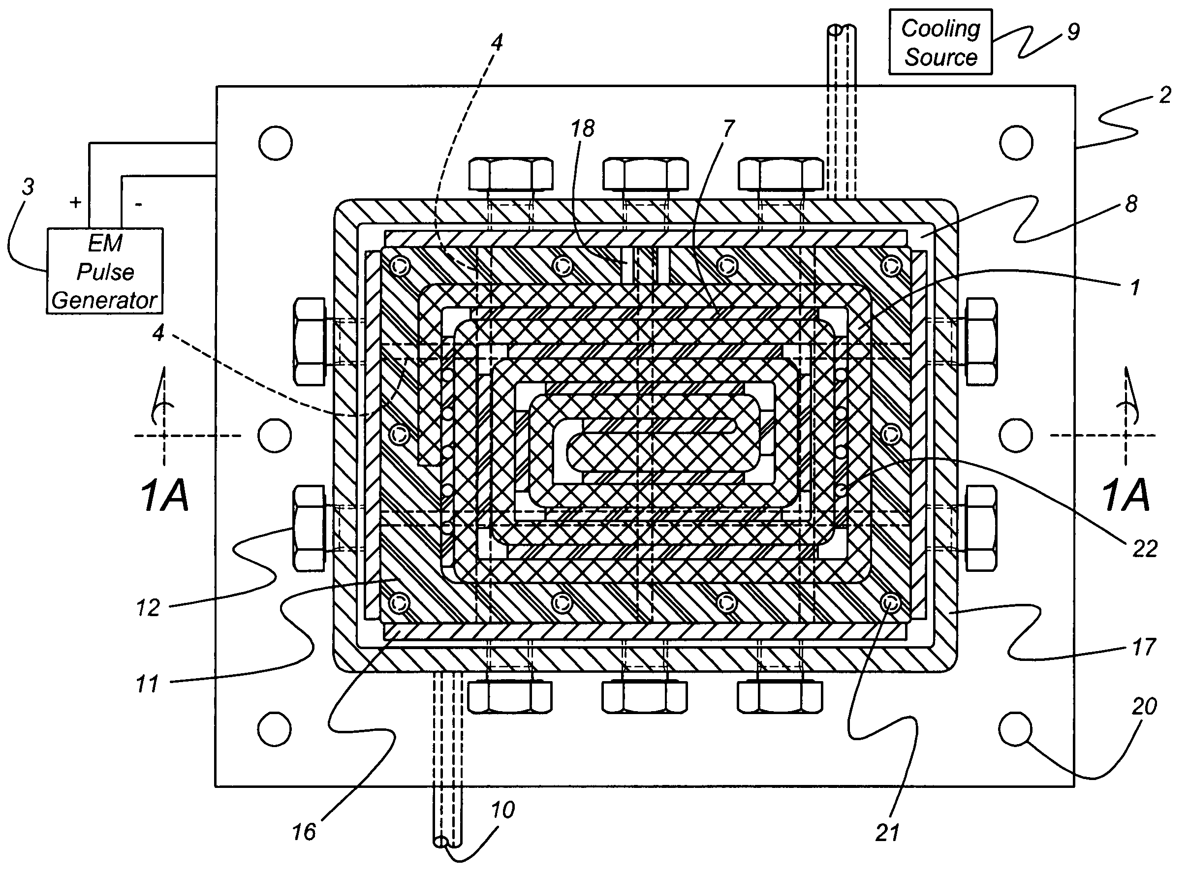
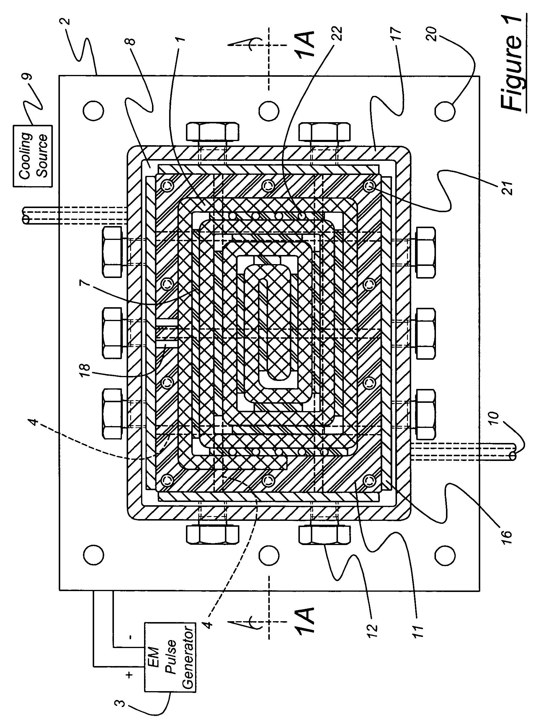
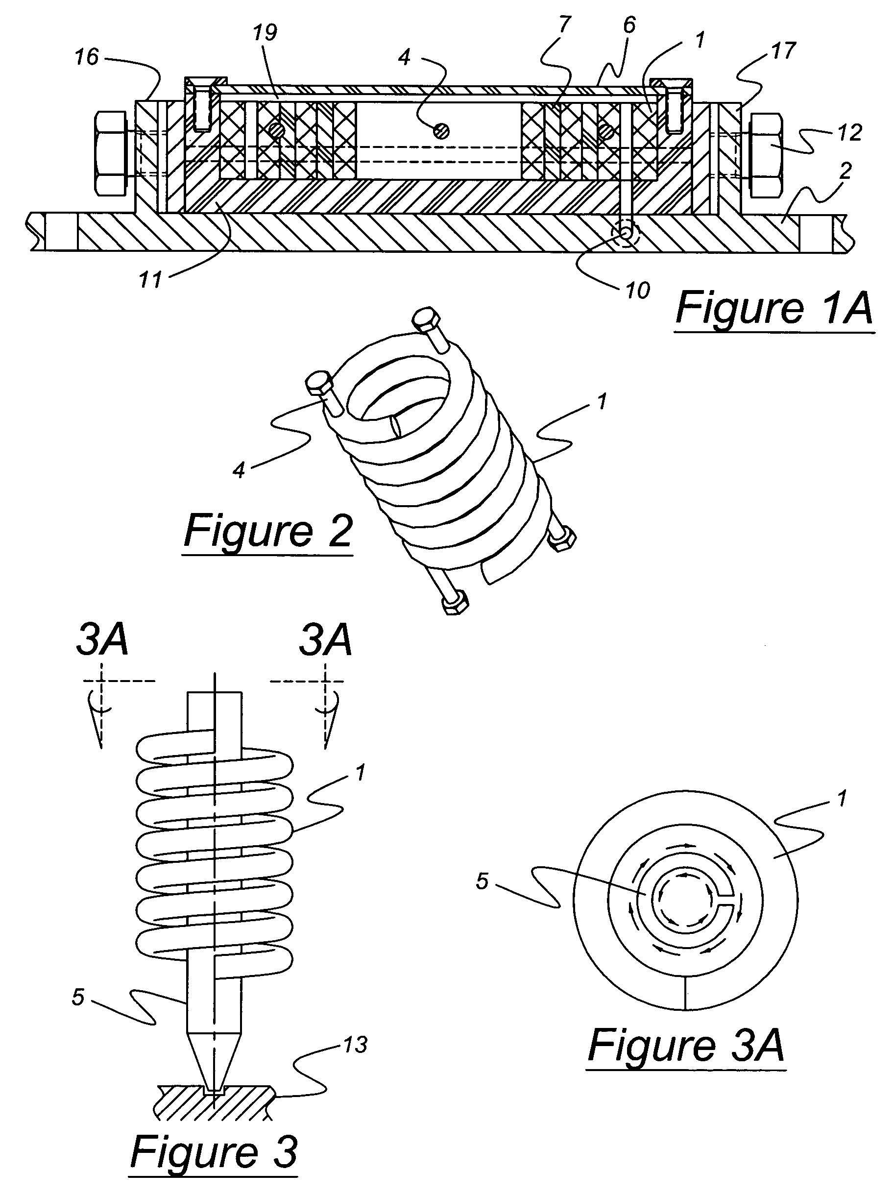
[0025]Referring now to the drawings, FIG. 1 illustrates a top plan view of an apparatus for the electromagnetic forming of a workpiece according to the present invention. Generally, electromagnetic forming machines force a workpiece into a die cavity either directly or indirectly by exerting force on a shaper that resultantly forms the workpiece. Electromagnetic Forming (“EMF”) will be used to describe all such processes herein.

[0026]The electromagnetic forming apparatus shown in FIG. 1 includes a multi-turn solenoid coil 1 framed by a housing unit 2 and insulative members 7 made from an electrically insulative material. The electric current for the EMF operation is generated by the electromagnetic pulse generator 3 and travels through the multi-turn coil 1. The coil 1 is connected to the electromagnetic pulse generator 3 and machined from an electrically conductive material with a high mechanical strength such as cold rolled steel or bronze. To prevent short-circuiting in the coil ...


PUM

PropertyMeasurementUnit
distanceaaaaaaaaaa
electromagnetic forceaaaaaaaaaa
electromagnetic fieldaaaaaaaaaa

Abstract

There is disclosed herein an apparatus for electromagnetic forming of a workpiece with enhancements that increase the durability and overall efficiency of the solenoid coil. The apparatus includes reinforcement members dispersed through the solenoid coil and a cooling system. The apparatus also includes a shaper that varies in girth effectively acting as a force concentrator. The electromagnetic forming device is also capable of incrementally heat treating the workpiece and reducing residual stresses in the workpiece. The invention further discloses a more efficient way of manufacturing the solenoid coil.

Description

BACKGROUND OF THE INVENTION[0001]1. Field of the Invention[0002]The present invention relates to an apparatus for the electromagnetic forming of materials as well as a method for manufacturing this apparatus.[0003]2. Description of Related Art[0004]Electromagnetic (EM) forming uses the pressure created by a pulsed electromagnetic field in combination with traditional sheet forming technologies on conventional presses to shape materials. An electromagnetic force is defined as a force developed by the passage of an electrical current. EM forming is typically accomplished by the use of an electric current source, a multi-turn solenoid coil and a die. The electrical current leaves from the source at one end of the coil and travels through the coil to the other end. During the high-voltage discharge of capacitors through the coil, a strong electromagnetic field is generated which induces eddy current in the workpiece. The interaction of electromagnetic fields generated by the direct curr...

Claims


Application Information

Patent Timeline
Patent Type & Authority Patents(United States)
IPC IPC(8): B21J15/24
CPCB21D26/14
Inventor GOLOVASHCHENKO, SERGEYDMITRIEV, VLADIMIRCANFIELD, PATRICKKRAUSE, ALBERTMARANVILLE, CLAY
Owner FORD GLOBAL TECH LLC
Learn More