
Illuminating warning lamp

a warning lamp and lamp technology, applied in the field of illumination warning lamps, can solve the problems of high installation and maintenance inconvenience, driving danger for both, and achieve the effects of reducing luminance, reducing driving safety, and high luminan

Inactive Publication Date: 2009-06-02
LIN YUNG FA
View PDF6 Cites 6 Cited by
  • Summary
  • Abstract
  • Description
  • Claims
  • Application Information

AI Technical Summary

Benefits of technology

"The present invention is an illuminating warning lamp with both warning and illumination effects. It includes a lamp socket, two light sources, two lamp casings, and a fixing ring. The first and second light sources are assembled on the lamp socket, and their irradiation directions form an angle of 90 degrees. The first lamp casing is assembled on the lamp socket, with a plurality of refractive surfaces that reduce the luminance of the first light source's lights. The second lamp casing is in a perfectly smooth configuration, with high luminance after transmitting through it. The first and second light sources are electrically connected to a power supply of the vehicle, and the second light source's irradiation direction is adjusted towards the ground. This design provides both warning and illumination lights, improving driving safety during traveling."

Problems solved by technology

Such two lamps are designed in total different manners, and they are mostly designed separately, which causes much inconvenience in both installation and maintenance, especially for some large scale vehicles such as touring cars, freight cars, trucks, or even sand and stone carriages.
An insufficient luminance makes the driver unable to see the roadside conditions clearly while reversing; whereas an excessively high luminance causes the driver of the approaching vehicle there behind unable to see the front road conditions clearly, thereby resulting in the driving danger for both parties.

Method used


Image

  • Illuminating warning lamp
  • Illuminating warning lamp
  • Illuminating warning lamp

Examples


Embodiment Construction

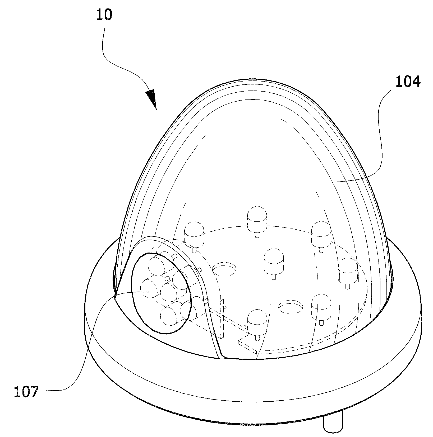
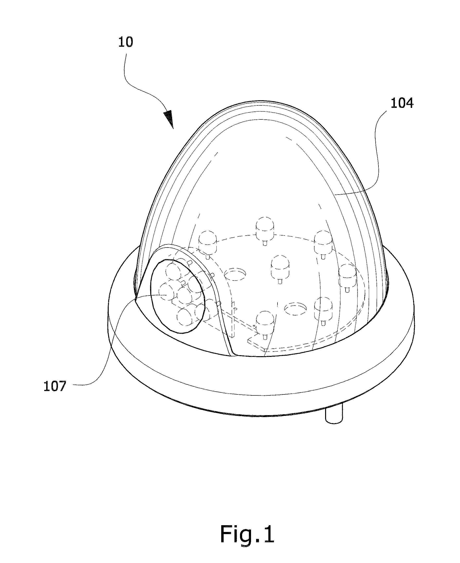
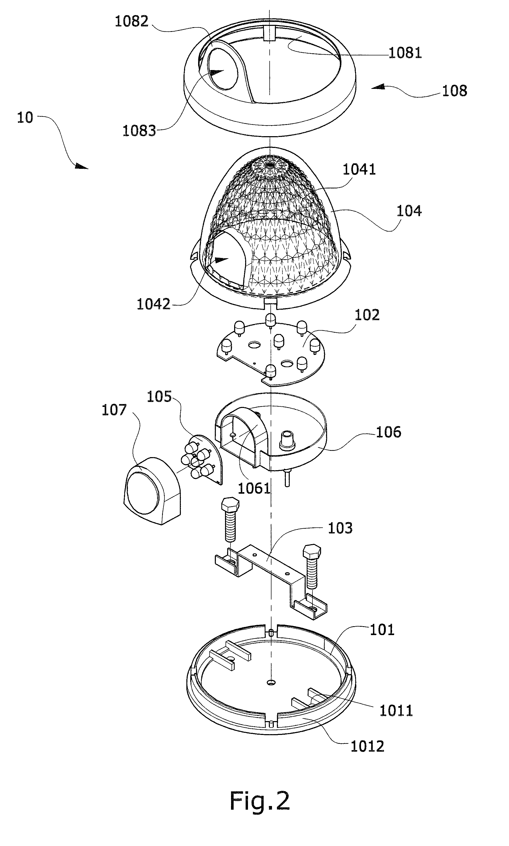
[0015]FIG. 1 is a three-dimensional assembled view of a preferred embodiment of the present invention. Referring to FIG. 1, when viewed from the front side of an illuminating warning lamp 10 of the present invention, a first lamp casing 104 and a second lamp casing 107 can be seen, which have different colors. The first lamp casing 104 is formed with a plurality of continuous refractive surfaces on a surface thereof. Two separate light sources are disposed inside the illuminating warning lamp 10. The two light sources may be electrically connected to a power supply of the car separately or electrically connected to the same power supply simultaneously. A switch may be further disposed to control the two light sources to emit lights separately or simultaneously. The lights emitted by the first lamp casing 104 serves as the warning lights, which have a low luminance and thus avoid the dizziness problem of a driver of a vehicle there behind and prevent the driver from seeing vehicles t...


PUM


Abstract

An illuminating warning lamp includes a first light source and a second light source assembled on a lamp socket. An irradiation direction of the first light source and that of the second light source form an angle of 90 degrees with respect to each other. Additionally, a first lamp casing for encapsulating the first light source is further formed with a through hole at one side thereof, and a second lamp casing corresponding to the second light source is assembled within the through hole. After the first and second light sources are both driven to emit lights, the lamp simultaneously emits warning lights and illumination light.

Description

BACKGROUND OF THE INVENTION[0001]1. Field of the Invention[0002]The present invention relates to an illuminating warning lamp assembled on a vehicle, and more particularly to an illuminating warning lamp with a light source for warning and a light source for illumination assembled within the same lamp socket, so as to simultaneously emit warning lights and illumination lights.[0003]2. Related Art[0004]Generally, a common vehicle utilizes several warning lamps and illumination lamps assembled on the periphery of the vehicle body when being used at night, for example, traveling or parking beside the road for a while at night. The warning lamps are provided for being viewed by a driver of a vehicle there behind, so that the driver keeps alert; whereas the illumination lamps are used for illuminating the road to ensure the safety of the vehicle when being used at night.[0005]However, since the usage and irradiation direction of the warning lights are different from that of the illuminat...

Claims


Application Information

Patent Timeline
Patent Type & Authority Patents(United States)
IPC IPC(8): B60Q1/00
CPCB60Q1/2607B60Q1/2696B60Q1/32B60Q1/52F21V33/0076F21Y2101/02F21Y2115/10
Inventor LIN, YUNG-FA
Owner LIN YUNG FA
Learn More