Temperature sensing device for selectively measuring temperature at desired locations along an intravenous fluid line

a temperature sensing device and fluid line technology, applied in the direction of contraceptive devices, instruments, heat measurement, etc., can solve the problems of increasing system complexity and cost, non-sterility of devices, and risk of injury, so as to facilitate the re-use of temperature sensors, facilitate the measurement of fluid temperature, and maintain fluid sterility

Inactive Publication Date: 2009-06-02
MEDICAL SOLUTIONS INC
View PDF319 Cites 24 Cited by
  • Summary
  • Abstract
  • Description
  • Claims
  • Application Information

AI Technical Summary

Benefits of technology

[0014]It is another object of the present invention to obtain an accurate and reliable temperature indication of fluid within an IV line at any desired location along that line and display the temperature indication to an operator.
[0015]Yet another object of the present invention is to removably secure a temperature sensing device to an IV line and facilitate measurement of fluid temperatures at varying locations along that line.
[0016]Still another object of the present invention is to facilitate re-use of a temperature sensor with a temperature sensing device to measure the temperature of sterile fluid while maintaining fluid sterility.

Problems solved by technology

In particular, the Magliochetti et al. and Carter, Jr. et al. systems employ temperature measurement in combination with temperature control, thereby increasing system complexity and costs to employ those systems for temperature measurement functio
ns. Further, the size and / or mounting requirements for those systems tend to restrict system application to particular sections of an IV l
ange. This tends to lead to inaccuracies in fluid temperature control and measurement for the desired sites, thereby risking injury to a pa
Accordingly, these devices are employed for non-sterile applications and are ill-suited for medical applications that require sterility.
Although these devices measure fluid temperature, the devices generally do not provide a displayed temperature to an operator.
Thus, fluids may attain inappropriate temperatures without notice to the operator which may lead to undesirable conditions or consequences.
This is distracting to the operator and permits possible operator error to be introduced with respect to the fluid temperature measurement, thereby enabling infusion of fluid at an inappropriate temperature and risking injury to the patient.

Method used


Image

  • Temperature sensing device for selectively measuring temperature at desired locations along an intravenous fluid line
  • Temperature sensing device for selectively measuring temperature at desired locations along an intravenous fluid line
  • Temperature sensing device for selectively measuring temperature at desired locations along an intravenous fluid line

Examples


Embodiment Construction

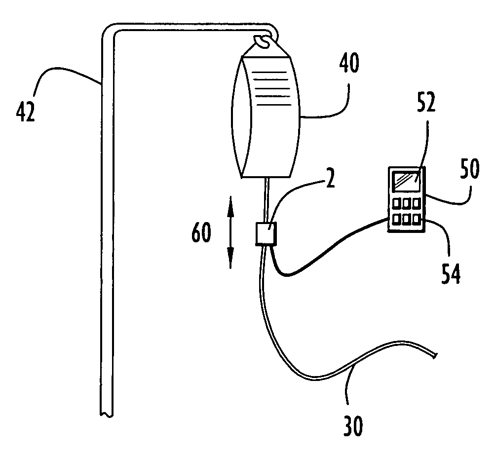
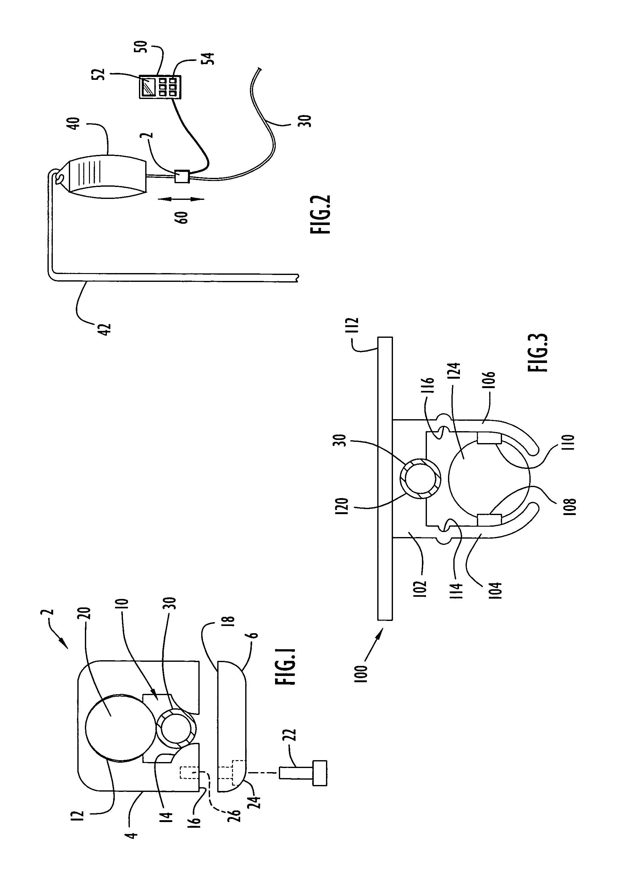
[0039]A temperature sensing device for measuring the temperature of a fluid within an IV fluid line at operator selected locations along the line is illustrated in FIG. 1. Specifically, a temperature sensing device 2 may be removably affixed around any selected portion of an IV line 30. The device includes a housing member 4 and a cap member 6, wherein each member is typically constructed of an appropriate material (e.g., plastic) having suitable insulative properties to ensure the accuracy of temperatures measured for the portion of a fluid line disposed between the housing and cap members. Housing member 4 has a generally rectangular configuration and includes a channel 10 extending between the longitudinal ends of the housing member and having suitable dimensions to receive a selected portion of fluid line 30 and a temperature sensor 20. However, the housing member may have any geometric configuration suitable for operation of the device as described below. Channel 10 typically i...


PUM

PropertyMeasurementUnit
temperatureaaaaaaaaaa
forceaaaaaaaaaa
temperaturesaaaaaaaaaa

Abstract

A temperature sensing device measures the temperature of a fluid at selected locations along an IV fluid line. The device is secured to a selected portion of the IV line and includes a temperature sensor for measuring fluid flowing within that line. The device is coupled to a temperature display device to display the measured temperature. The temperature sensing device may include: a housing with a lower cover to engage the line and a temperature sensor; a holder movable along the line and including a temperature sensor; a housing with a lower member including a tip to pierce and measure temperature of fluid within the line; a resilient member with a spiral configuration and a tip to pierce and measure temperature of fluid within the line; a ‘T’-type fitting including a temperature sensor; or a ‘Y’-type fitting including a temperature sensor in the form of a needle.

Description

CROSS REFERENCE TO RELATED APPLICATIONS[0001]This application is a divisional of U.S. patent application Ser. No. 09 / 973,988, entitled “Temperature Sensing Device for Selectively Measuring Temperature at Desired Locations Along an Intravenous Fluid Line” and filed Oct. 11, 2001, now U.S. Pat. No. 7,090,658, which is a continuation-in-part of U.S. patent application Ser. No. 09 / 380,507, filed Apr. 24, 2000, entitled “Method and Apparatus for Pressure Infusion and Temperature Control of Infused Liquids”, now U.S. Pat. No. 6,824,528 which is a National Stage Application of PCT International Application No. PCT / US98 / 04199, filed Mar. 3, 1998, entitled “Method and Apparatus for Pressure Infusion and Temperature Control of Infused Liquids”, which claims priority from U.S. Provisional Patent Application Ser. Nos. 60 / 040,885, filed Mar. 3, 1997, entitled “Method and Apparatus for Measurement and Control of Temperature for Infused Liquids” and 60 / 062,315, filed Oct. 17, 1997, entitled “Metho...

Claims


Application Information

Patent Timeline
Patent Type & Authority Patents(United States)
IPC IPC(8): A61M31/00A61F7/12G01K1/08A61B5/01A61M5/14A61M5/148A61M5/168A61M5/172A61M5/44
CPCA61M5/14A61M5/1483A61M5/44A61M5/445A61M5/1689A61M5/172A61M2205/3368A61M2205/3653A61M2209/04G01K1/143
Inventor FARIES, JR., DURWARD I.HEYMANN, BRUCE R.BLANKENSHIP, CALVINHENDRIX, DAVID
Owner MEDICAL SOLUTIONS INC
Why Eureka
Try Eureka