Flying height measurement and control with user data signal

a technology of user data and height measurement, applied in the field of determining can solve the problems of mechanical resonance of the head, oscillating movement of the head, and the change of the flying height of the head

Inactive Publication Date: 2009-06-02
SAMSUNG ELECTRONICS CO LTD
View PDF7 Cites 42 Cited by
  • Summary
  • Abstract
  • Description
  • Claims
  • Application Information

AI Technical Summary

Problems solved by technology

For example, a shock load on the drive may create a vibration that causes the heads to mechanically resonate.
Particles or scratch ridges in the disk may also cause oscillating movement of the heads.
Environment changes, such as temperature and altitude can also cause a change in the head flying height.
The varying magnetic field strength may result in poor writing of data.
Errors will occur when the signal is read back by the drive.
Practical construction of spacing error signals (“SES”) is limited by available electrical / mechanical signals and disk drive hardware capability.
Data AGC schemes are also susceptible to variations because of temperature.

Method used


Image

  • Flying height measurement and control with user data signal
  • Flying height measurement and control with user data signal
  • Flying height measurement and control with user data signal

Examples


Embodiment Construction

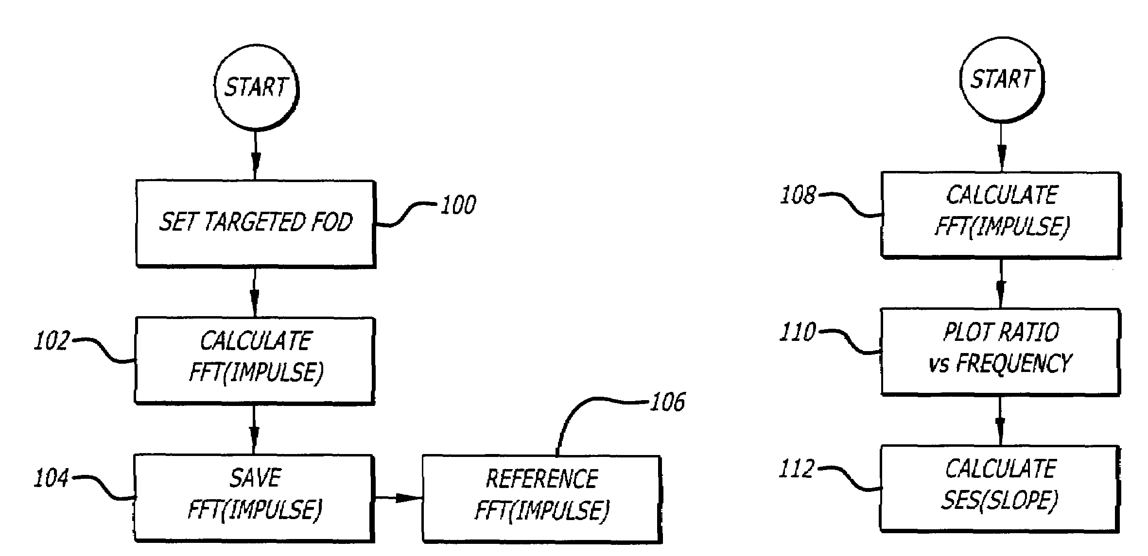
[0019]Disclosed is a hard disk drive that determines a flying height from a slope of a line created from a ratio of amplitudes of frequencies in response to impulse functions. The impulse function (or also known as impulse response) can be a playback waveform de-convolved by channel data sequence. Channel data is the binary sequence based on which the track on the disk is magnetized. In Fourier space, this can be easily written as following:

FFT(impulse function)=FFT(playback_waveform) / FFT(channel_data)   (1)

[0020]A first set of amplitudes of reference frequencies can be determined from a reference impulse. A second set of amplitudes of data frequencies can be determined from a data impulse during operation of the disk drive. Ratios of the amplitudes of the data and reference frequencies at different discrete frequencies can be plotted. The slope of the plotted line corresponds to the difference between the flying height when the reference impulse is generated and the flying height w...


PUM

PropertyMeasurementUnit
harmonic frequencyaaaaaaaaaa
flying heightaaaaaaaaaa

Abstract

A hard disk drive that determines a flying height from a slope of a line created from a ratio of amplitudes of frequencies in response to impulse functions. A first set of amplitudes of reference frequencies can be determined from a reference impulse. A second set of amplitudes of data frequencies can be determined from a data impulse during operation of the disk drive. Ratios of amplitudes of the data and reference frequencies at different discrete frequencies can be plotted. The slope of the plotted line corresponds to the difference between the flying height when the reference impulse is generated and the flying height when the data impulse is generated. The disk drive may utilize the slope in a feedback routine to control the flying height.

Description

BACKGROUND OF THE INVENTION[0001]1. Field of the Invention[0002]The present invention relates to determining a flying height of a head in a hard disk drive.[0003]2. Background Information[0004]Hard disk drives contain a plurality of magnetic heads that are coupled to rotating disks. The heads write and read information by magnetizing and sensing the magnetic fields of the disk surfaces. Each head is attached to a flexure arm to create a subassembly commonly referred to as a head gimbal assembly (“HGA”). The HGA's are suspended from an actuator arm. The actuator arm has a voice coil motor that can move the heads across the surfaces of the disks.[0005]HGA transducers include three primary elements: a reader sensor, a writer structure and a head protrusion control element, also known as fly-on-demand (“FOD”). The reader sensor is commonly made of a spinning tunneling MR structure. The writer structure includes coils and magnetic flux path structure made with high permeability and high ...

Claims


Application Information

Patent Timeline
Patent Type & Authority Patents(United States)
IPC IPC(8): G11B21/02
CPCG11B5/6005G11B5/6029
Inventor CHE, XIAODONGTANG, YAWSHING
Owner SAMSUNG ELECTRONICS CO LTD
Why Eureka
Try Eureka